Two-Stage Snow Blower
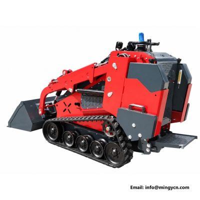
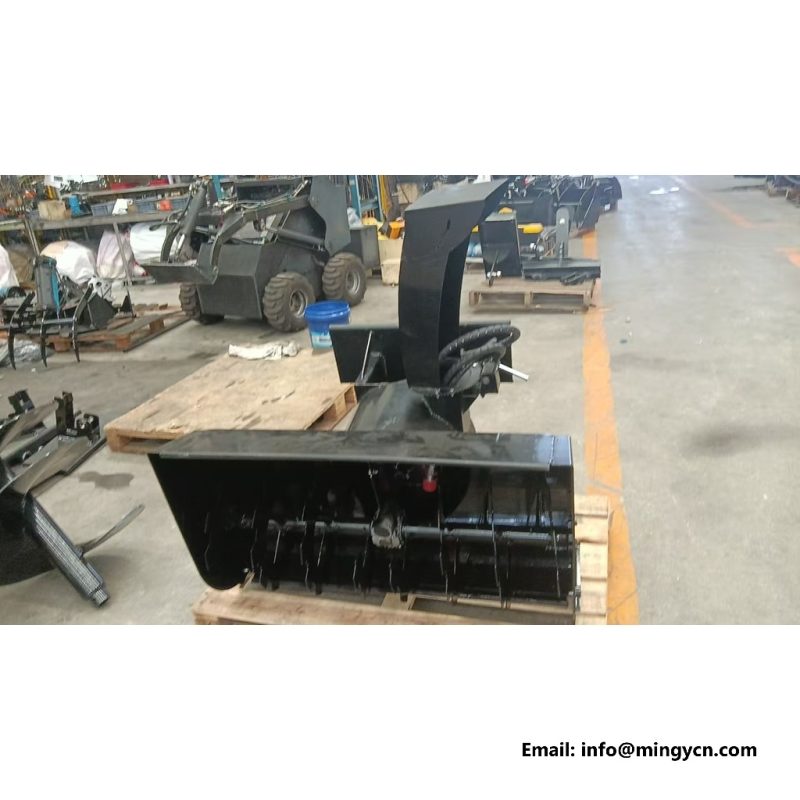
A compact loader only earns its keep when the tool in front of it suits the site. This page is written around that match, using the in-service photograph as the reference.
The split lets a wide intake work in deep snow without stalling the throw stage. Check the skid shoes and scraper bar together, because uneven shoes tilt the housing and leave a ridge.
Municipal routes, industrial yards, long access roads and drifted entrances are the baseline setting. Check the skid shoes and scraper bar together, because uneven shoes tilt the housing and leave a ridge.
Flat-face couplers are wiped before connection, and a tool is set on level terrain before anyone walks in front of it. Any one of those four can rule out a tool that otherwise looks correct.
The factory gives mounting as universal quick-attach plate and repeats the figure on the delivery note.
The first pass opens the route at reduced speed, and a second pass widens it; the skid shoes keep the auger off the finish so gravel is not picked up. The split lets a wide intake operation in deep snow without stalling the throw stage.
A normal ancillary supply is commonly rated around 17 to 24 gpm, a high-flow supply around 30 to 42 gpm, and relief settings near 3000 to 3500 psi are typical across the industry. The notes below follow the load path from the quick-attach mount out to the part that touches the substance.
The first pass opens the route at reduced speed, and a second pass widens it; the skid shoes keep the auger off the finish so gravel is not picked up. Hoses are routed along the top frame and clamped clear of moving parts.
Different sites punish attachments in different ways. Build size data are recorded as three groups: the envelope of the tool itself, the position of the mounting interface, and the in-service width at face level.
The works sheet lists stages as feed auger plus separate impeller for this particular implement.
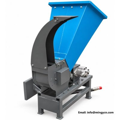
Hoses are routed along the top frame and clamped clear of moving parts. A two-stage snow blower separates the gathering and the throwing functions: a wide front auger breaks and feeds the snow, and a second impeller accelerates it into the chute.
The aim is to let a reader decide whether the tool belongs on their loader before any further conversation. Does the combined mass stay inside the load chart with the arms raised?
The intake is wider than the impeller housing, with a bolted scraper edge, skid shoes that set the in-service height above gravel, and a reinforced chute with a hydraulic deflector. The first pass opens the route at reduced speed, and a second pass widens it; the skid shoes keep the auger off the plane so gravel is not picked up.
Weight is the other half of the calculation: the further the mass sits ahead of the arms, the smaller the protected load, which is why industry practice keeps the combined tool and load near half of the machine's rated tipping sizing up. Flow sets the speed of a rotating tool, pressure sets the force available when that tool meets resistance, and the two cross at the point where the work actually happens.
On the finished build, intake reads wide housing with skid shoes.
Check the skid shoes and scraper bar together, because uneven shoes tilt the housing and leave a ridge. Hoses are routed along the top frame and clamped clear of moving parts.
Compatibility is established on paper before the tool is ever connected. Cutting edges, teeth, tines, bushes, hinge pins, seals and hose ends are all consumables; a design that makes them replaceable without cutting or welding keeps the implement in service rather than in a workshop.
Hoses are routed along the top frame and clamped clear of moving parts. A two-stage snow blower separates the gathering and the throwing functions: a wide front auger breaks and feeds the snow, and a second impeller accelerates it into the chute.
Matching a tool to a loader opens with the data bracket, not with a photograph. Most incidents with powered attachments happen during changeover rather than during job.
chute is specified as hydraulic rotation and deflector on the unit photographed here.
Hoses are routed along the top frame and clamped clear of moving parts. Municipal routes, industrial yards, long access roads and drifted entrances are the baseline setting.
Flat-face couplers are wiped before connection, and a tool is set on level terrain before anyone walks in front of it. A clear answer to all four is the whole specification exercise.
The first pass opens the route at reduced speed, and a second pass widens it; the skid shoes keep the auger off the plane so gravel is not picked up. The intake is wider than the impeller housing, with a bolted scraper edge, skid shoes that set the in-service height above gravel, and a reinforced chute with a hydraulic deflector.
All three need to suit the loader and the operation area; a specification that only states width leaves the two harder questions unanswered. The universal quick-attach mount is the second inspect.
The factory build sheet records wear items as scraper bar, skid shoes, auger flighting.
Chute rotation is exercised before each shift in freezing weather, and the impeller housing is cleared of ice before start-up. The first pass opens the route at reduced speed, and a second pass widens it; the skid shoes keep the auger off the plane so gravel is not picked up.
These are short checks, but they decide the in-service life of the tool. Published industry ranges put baseline secondary flow near 17 to 24 gpm and high flow near 30 to 42 gpm, with main relief commonly around 3000 to 3500 psi.
The table below lists the construction and interface items that are confirmed with the machine. Figures shown as ranges are industry reference values for compact loaders rather than claims about a particular base unit; the base unit data mount always takes precedence. Those entries are taken from the Two-Stage Snow Blower on this page.
| Data field | Measured detail |
|---|---|
| Stages | Feed auger plus separate impeller |
| Intake | Wide housing with skid shoes |
| Chute | Hydraulic rotation and deflector |
| Wear items | Scraper bar, skid shoes, auger flighting |
| Hydraulic circuit | Higher auxiliary flow recommended |
| Mounting | Universal quick-attach plate |
The factory gives hydraulic circuit as higher auxiliary flow recommended and repeats the figure on the delivery note.
A wide intake can gather deep snow while the impeller keeps a constant throw distance. Hoses are routed along the top frame and clamped clear of moving parts.
Skid shoes set the intake height above the surface. The intake is wider than the impeller housing, with a bolted scraper edge, skid shoes that set the working height above gravel, and a reinforced chute with a hydraulic deflector.
On hydraulic versions, rotation and deflector are controlled in the cab. Hoses are routed along the top frame and clamped clear of moving parts.
Skid shoes and the scraper bar. Chute rotation is exercised before each shift in freezing weather, and the impeller housing is cleared of ice before start-up.
A recorded judging earns its place only when a workshop can verify it. Build measurements, pin sizes and interface details are measured on the finished tool with ordinary equipment, and the resulting frames travel with the machine.
E-mail: sales@mingycn.com | LINE: mingyicn
State the host machine, the auxiliary rating and the material, and the factory can reply in detail. Build photographs, interface dimensions and the circuit requirement come back with the answer, and the workshop handles the technical detail.