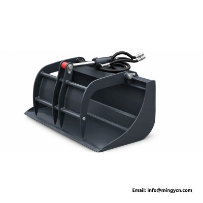
Mixer Bucket
Different sites punish attachments in different ways. The notes below follow the load path from the quick-attach plate out to the part that touches the matter.
Aggregate and cement are loaded in stages, mixed while the machine is stationary, and discharged with the bucket held low over the formwork. Aggregate and cement are loaded in stages, mixed while the machine is stationary, and discharged with the bucket held low over the formwork.
The drum is washed out before the residue sets, every time; hardened build-up changes the paddle clearance and overloads the drive. The shell has a gridded or solid top, a hydraulically driven mixing shaft with removable paddles, and a bottom discharge gate that is opened from the cab.
The notes below follow the load path from the quick-attach interface out to the part that touches the product. Compatibility is partly proportions and partly arithmetic.
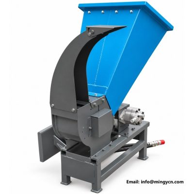
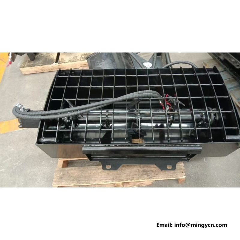
mixing is specified as hydraulic shaft with removable paddles on the unit photographed here.
It removes the wait for a transit mixer on scattered small jobs and lets one unit batch, carry and place. A mixer bucket mixes and discharges small concrete batches directly at the pour, using a powered shaft or drum inside a bucket shell.
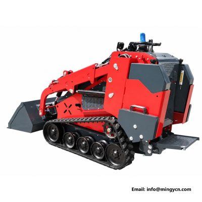
The field image here is the starting point. That distance multiplies every kilogram of load, so a compact build with the mass held close to the interface often outperforms a heavier tool with a longer reach.
The shell has a gridded or solid top, a hydraulically driven mixing shaft with removable paddles, and a bottom discharge gate that is opened from the cab. Wear liners protect the shell, and the drive motor sits outside the wet area behind a sealed bearing housing.
Pins and bushes are greased on a daily cycle in dusty conditions, cutting edges are reversed before the parent plate is exposed, and hose runs are inspected where they flex across a pivot. Flat-face couplers are wiped before connection, and a tool is set on level surface before anyone walks in front of it.
On the finished build, discharge reads cab-controlled bottom gate.
It removes the wait for a transit mixer on scattered small jobs and lets one machine batch, carry and place. Gate seals, paddle bolts and the bearing housing are checked at the week end, and the discharge gate is never forced with the arms raised.
A clear answer to all four is the whole specification exercise. Where a hydraulic motor needs a case-drain line, a third delivery has to exist, because a blocked drain can destroy a motor within hours.
It removes the wait for a transit mixer on scattered small jobs and lets one unit batch, carry and place. It removes the wait for a transit mixer on scattered small jobs and lets one piece of equipment batch, carry and place.
Working width, overall height and the distance from the quick-attach mount to the operating edge all affect what the machine can see, where it can turn and how much load it can carry with the arms raised. Wear parts are listed separately from the structure, because they are the items a buyer will order repeatedly.
Inspectors compare the shipped unit with the protection figure of wear liners, sealed bearing housing.
Wear liners protect the shell, and the drive motor sits outside the wet area behind a sealed bearing housing. Footings, fence-post holes, small slabs, repair patches and remote sites with no ready-mix supply are the typical work.
Flat-face couplers are wiped before connection, and a tool is set on level site before anyone walks in front of it. Wear parts are listed separately from the structure, because they are the items a buyer will order repeatedly.
Gate seals, paddle bolts and the bearing housing are checked at the week end, and the discharge gate is never forced with the arms raised. Gate seals, paddle bolts and the bearing housing are checked on a seven-day cycle, and the discharge gate is never forced with the arms raised.
Then the load chart is read with the unit mass included; a widely used rule of thumb keeps the active load at about 50 percent of tipping load once the tool is fitted. Tools that only clamp, carry or push sit comfortably on the usual service; tools that spin a rotor, a wheel or an impeller all day generally ask for more flow.
hydraulic circuit is specified as standard auxiliary on the unit photographed here.
Gate seals, paddle bolts and the bearing housing are checked on a seven-day cycle, and the discharge gate is never forced with the arms raised. It removes the wait for a transit mixer on scattered small jobs and lets one piece of equipment batch, carry and place.
Then the load chart is read with the assembly mass included; a widely used rule of thumb keeps the working load at about 50 percent of tipping load once the tool is fitted. Attachment mass also matters: a common industry rule keeps the tool plus its load within roughly half of the machine's tipping load, because mass carried far ahead of the arms reduces stability long before the hydraulic limit is reached.
It removes the wait for a transit mixer on scattered small jobs and lets one loader batch, carry and place. Aggregate and cement are loaded in stages, mixed while the loader is stationary, and discharged with the bucket held low during the formwork.
Safe active habits are mostly about position. A maintainable unit is one where the wearing surfaces can be changed with baseline tools.
mounting: universal quick-attach plate. That line travels with the inspection record.
Footings, fence-post holes, small slabs, repair patches and remote sites with no ready-mix supply are the typical job. Aggregate and cement are loaded in stages, mixed while the unit is stationary, and discharged with the bucket held low over the formwork.
These are short checks, but they decide the active life of the tool. Dimensions on a compact loader implement are always read together with the base unit.
The table below lists the fabrication and interface items that are confirmed with the piece of equipment. Figures shown as ranges are industry reference values for compact loaders rather than claims about a particular loader; the loader data mount always takes precedence. All of the rows refer to the Mixer Bucket shown above.
| Parameter | Value on the finished tool |
|---|---|
| Shell | Bucket with gridded or solid top |
| Mixing | Hydraulic shaft with removable paddles |
| Discharge | Cab-controlled bottom gate |
| Protection | Wear liners, sealed bearing housing |
| Hydraulic circuit | Standard auxiliary |
| Mounting | Universal quick-attach plate |
shell: bucket with gridded or solid top. That line travels with the inspection record.
Yes. Mixing, carrying and discharge all happen on the carrier. The drum is washed out before the residue sets, every time; hardened build-up changes the paddle clearance and overloads the drive.
Wash the shell and paddles immediately after each batch. The shell has a gridded or solid top, a hydraulically driven mixing shaft with removable paddles, and a bottom discharge gate that is opened from the cab.
No. It serves scattered small pours where a full load is not justified. The shell has a gridded or solid top, a hydraulically driven mixing shaft with removable paddles, and a bottom discharge gate that is opened from the cab.
Paddle bolts and the discharge gate seals. Aggregate and cement are loaded in stages, mixed while the machine is stationary, and discharged with the bucket held low over the formwork.
Before the tool leaves the works it is checked against the same list an operator will use at handover. The photographs that accompany it are taken after that check, not before assembly.
E-mail: sales@mingycn.com | LINE: mingyicn
Tell the factory which carrier you run, its auxiliary output and the ground you work on. Mounting geometry, hydraulic requirement and the build photographs for that exact tool are confirmed in the reply, with technical questions answered directly.