Concrete Mixer Drum
The field image here is the starting point. Everything that follows describes what a driver will see, hear and inspect during a normal working day with this implement.
Mixing is done at a steady drum speed, and the pour is controlled by tipping rather than by pushing the machine forward. Drive chain tension, tilt yoke pins and motor mounts are checked on a weekly cycle.
It is the closest tool to a conventional small mixer, but carried and powered by the loader hydraulics. Small structural pours, mortar operation, repair crews and sites where the mix is made beside the placement point all suit the drum.
They need to know how it behaves on the ground they have, which is what the sections below set out. A wider tool is not automatically a better tool on a narrow task area.
The factory build sheet records frame as tilting yoke with transport lock.
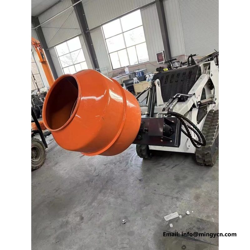
It is the closest implement to a conventional small mixer, but carried and powered by the loader hydraulics. The drum is a welded cone-cylinder shell with internal spiral fins, a chain or gear drive from a hydraulic motor, and a tilting yoke with a lock.
A useful checklist asks four questions in order. Attachment mass also matters: a common industry rule keeps the tool plus its load within roughly half of the base unit's tipping load, because mass carried far ahead of the arms reduces steadiness long before the hydraulic limit is reached.
The drum is a welded cone-cylinder shell with internal spiral fins, a chain or gear drive from a hydraulic motor, and a tilting yoke with a lock. The frame keeps the drum mouth clear of the loader arms through the full tip angle.
Matching a tool to a carrier commences with the data interface, not with a photograph. The views on this page show the tool as it is built and used, not a styled render.
hydraulic circuit is specified as standard auxiliary on the unit photographed here.
Mixing is done at a steady drum speed, and the pour is controlled by tipping rather than by pushing the machine forward. Small structural pours, mortar work, repair crews and sites where the mix is made beside the placement point all suit the drum.
That distance multiplies every kilogram of load, so a compact construction with the mass held close to the interface often outperforms a heavier tool with a longer reach. The selection sequence is short: settle the unit's rated operating capacity, read the tool flow and pressure from its data bracket, measure the mounting bracket, then verify that the in-service width suits the job.
Drive chain tension, tilt yoke joint pins and motor mounts are checked on a weekly cycle. The drum is a welded cone-cylinder shell with internal spiral fins, a chain or gear drive from a hydraulic motor, and a tilting yoke with a lock.
Buyers who already run a loader rarely need a definition of the tool. Working width, overall height and the distance from the quick-attach mount to the active edge all affect what the piece of equipment can see, where it can turn and how much load it can carry with the arms raised.
Anyone reading the identification plate will find mounting given as universal quick-attach plate.
The frame keeps the drum mouth clear of the loader arms through the full tip angle. The frame keeps the drum mouth clear of the loader arms through the full tip angle.
The quick coupler accepts a baseline interface, but the locking wedges must seat fully and the interface must not be bent from a previous impact. Width is then checked against gate openings, transport limits and the machine's own track.
The frame keeps the drum mouth clear of the loader arms through the full tip angle. The frame keeps the drum mouth clear of the loader arms through the full tip angle.
Then the load chart is read with the assembly mass included; a widely used rule of thumb keeps the active load at about 50 percent of tipping load once the tool is fitted. A useful checklist asks four questions in order.
For drum the data sheet states welded cone-cylinder with internal fins; the same entry is read again at handover.
The frame keeps the drum mouth clear of the loader arms through the full tip angle. It is the closest assembly to a conventional small mixer, but carried and powered by the loader hydraulics.
Then the load chart is read with the tool mass included; a widely used rule of thumb keeps the operating load at about 50 percent of tipping load once the tool is fitted. Flat-face couplers are wiped before connection, and a tool is set on level site before anyone walks in front of it.
Fins and drum wall are washed immediately after use; a hardened layer reduces the effective volume and unbalances the rotation. The drum is a welded cone-cylinder shell with internal spiral fins, a chain or gear drive from a hydraulic motor, and a tilting yoke with a lock.
The universal quick-attach interface is the second inspect. No adjustment, clearing or greasing is attempted with the system pressurised, and flexible lines are relieved before a coupler is disconnected.
The factory build sheet records drive as hydraulic motor via chain or gear.
Fins and drum wall are washed immediately after use; a hardened layer reduces the effective volume and unbalances the rotation. A concrete mixer drum is a rotating drum on a tilting frame that mixes by lifting and dropping the mix through internal fins, then tips to pour.
Cutting edges, teeth, tines, bushes, hinge pins, seals and hose ends are all consumables; a design that makes them replaceable without cutting or welding keeps the tool in service rather than in a workshop. No adjustment, clearing or greasing is attempted with the loop pressurised, and hoses are relieved before a coupler is disconnected.
The table below lists the fabrication and interface items that are confirmed with the loader. Figures shown as ranges are industry reference values for compact loaders rather than claims about a particular base unit; the base unit data plate always takes precedence. The Concrete Mixer Drum is the unit those rows belong to.
| Parameter | Value on the finished tool |
|---|---|
| Drum | Welded cone-cylinder with internal fins |
| Drive | Hydraulic motor via chain or gear |
| Discharge | Hydraulic or manual tip yoke |
| Frame | Tilting yoke with transport lock |
| Hydraulic circuit | Standard auxiliary |
| Mounting | Universal quick-attach plate |
Before dispatch, the discharge entry is confirmed as hydraulic or manual tip yoke.
The drum rotates the whole mix; the bucket uses paddles inside a fixed shell. It is the closest attachment to a conventional small mixer, but carried and powered by the loader hydraulics.
Yes, controlled tipping at low height suits small placements. Fins and drum wall are washed immediately after use; a hardened layer reduces the effective volume and unbalances the rotation.
The rated operating capacity of the carrier, not the drum volume alone. The drum is a welded cone-cylinder shell with internal spiral fins, a chain or gear drive from a hydraulic motor, and a tilting yoke with a lock.
Drive chain, tilt pins and internal fins. The drum is a welded cone-cylinder shell with internal spiral fins, a chain or gear drive from a hydraulic motor, and a tilting yoke with a lock.
Before the tool leaves the works it is checked against the same list a person at the controls will use at handover. The images that accompany it are taken after that inspect, not before assembly.
E-mail: sales@mingycn.com | LINE: mingyicn
A short note with the carrier model, flow figure and working material is enough to start. Mounting geometry, hydraulic requirement and the build photographs for that exact tool are confirmed in the reply, with technical questions answered directly.