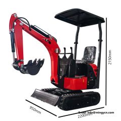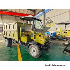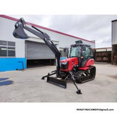
Hydraulic specifications are the part of a machine brochure most buyers skip, and the part that decides whether an attachment will actually work once it is on the machine and the job is waiting. A breaker that hammers weakly, an auger that stalls in stiff ground, a tilt hitch that moves slowly enough to be annoying — all three usually trace back to a mismatch between what the tool needs and what the carrier's hydraulic system delivers. Understanding four numbers is enough to avoid almost all of those mismatches, and they are not difficult numbers.
Four Numbers That Explain Almost Everything
Every hydraulic discussion comes back to flow, pressure, circuit type, and relief setting. Flow, measured in litres per minute, decides speed. Pressure, measured in bar or megapascals, decides force. Circuit type decides whether flow is available on demand or shared through a valve. And the relief setting decides where the system stops pushing and dumps flow as heat.
| Number | Unit | What it decides | Typical compact range |
|---|---|---|---|
| Flow | L/min | How fast a function moves; whether a motor-driven tool reaches working speed | 20 to 120 L/min on compact machines |
| Pressure | bar / MPa | How much force a cylinder or motor can produce | 160 to 280 bar common |
| Circuit type | open centre, closed centre, load sensing | Whether flow is shared, on demand, or pressure-compensated | Varies by machine class |
| Relief setting | bar | The ceiling; above it, energy becomes heat rather than work | Set per circuit by the manufacturer |
Flow Is Speed, Pressure Is Force
The clearest way to hold onto this: flow tells you how fast a cylinder extends or a motor spins, because a cylinder of a given bore needs a certain volume of oil to move a certain distance. Pressure tells you how much load that movement can overcome, because force is pressure multiplied by area. Double the flow to a cylinder and it moves twice as fast. Double the pressure and it pushes twice as hard, but not any faster.
This distinction explains most attachment frustrations. A hydraulic breaker needs flow to strike at the right rate; give it pressure without flow and it hits slowly and weakly. A hydraulic motor on an auger needs both: flow for speed and pressure for torque. A tilt or rotate function that feels sluggish is usually flow-starved, not pressure-starved.
Where Auxiliary Flow Comes From
On a compact machine, the auxiliary circuit is the supply that runs attachments. It may be a dedicated pump, a shared pump with a priority valve, or a circuit tapped from the main valve block. What matters to a buyer is how much flow is available at the couplers, at what pressure, and whether that supply continues while other functions are used.
Ask specifically: is the auxiliary circuit single-acting or double-acting; is there a case drain line, which motor-driven tools need; is flow adjustable from the cab; and is there a third or fourth circuit for tools with two motions. A machine with one auxiliary circuit can run a breaker well and a tilt-and-rotate poorly, because the second motion needs a second circuit or a diverter valve.
Reading a Spec Sheet Honestly
Brochures tend to print maximum flow, which is measured at a particular engine speed and often with no load. The useful figure is flow at the couplers under working conditions. Two habits help. First, ask for flow and pressure measured at the auxiliary couplers, not at the pump. Second, ask what happens to that flow when the machine is hot and the engine is at working speed rather than maximum speed.
The same caution applies to pressure. A relief setting is a ceiling, not a delivered figure; the system only reaches it when the load demands it. A tool rated for a pressure range should sit comfortably inside what the carrier can deliver continuously, not at the very top of it, because continuous operation at the relief setting turns the surplus into heat.
Heat: The Failure Nobody Schedules
Hydraulic systems make heat whenever flow passes over a relief valve instead of doing work. Continuous relief is the fastest way to overheat oil, and overheated oil thins, loses its film strength, oxidises, and destroys seals and pumps. The symptoms appear as slower functions when hot, a dark or burnt smell in the oil, and eventually leaks and component failure.
Practical prevention is unglamorous: keep the oil cooler clean and unobstructed, keep the correct oil level, use the viscosity the manufacturer specifies for your climate, and do not hold a function against the relief any longer than necessary. On a machine working a breaker or a mulcher for hours, an oil temperature gauge or warning is a specification worth asking for rather than an accessory.
Filtration and Oil Condition
Hydraulic components are built to clearances measured in microns, which is why filtration is a specification and not a consumable afterthought. Return filters, suction strainers, and sometimes pressure filters all have a job. Replace them on the interval, replace them with the correct rating, and never start a machine with a bypassed filter because you do not have the right one on site.
Water and particles are the two enemies. Water enters through breathers, condensation in partly filled tanks, and poor storage; it shows as milky oil and causes corrosion and loss of film strength. Particles enter through contaminated top-up oil, dirty fittings, and open lines during maintenance. The single most effective habit is to keep everything — funnel, drum, caps, fittings — clean before it touches the system.
Symptoms and What They Usually Mean
| Symptom | Likely cause | First check |
|---|---|---|
| Functions slow when hot | Internal leakage past worn pump, motor, or valve clearances | Oil temperature, oil condition, filter condition |
| One function weak, others normal | Cylinder bypass, or relief on that circuit | Cylinder drift test and circuit relief setting |
| Relief chatters or squeals | Relief valve set incorrectly or contaminated | Setting against specification; oil cleanliness |
| Attachment runs slow but strong | Flow too low for the tool | Measured flow at the couplers against tool requirement |
| Attachment fast but stalls under load | Pressure or flow insufficient for torque demand | Pressure at the couplers under load |
| Foaming or milky oil | Air ingress or water contamination | Suction line, breather, tank level, oil sample |
| Drifting cylinders when parked | Load-hold valve or cylinder seal leakage | Drift measurement over a fixed period |
Matching Tools to the Carrier
Before buying any hydraulic tool, write down three numbers from the carrier: flow at the couplers, pressure at the couplers, and the number of circuits. Then ask the tool supplier for the tool's required flow range and operating pressure, and check that the carrier sits inside it. If the tool needs a case drain and the machine does not have one, the tool will destroy its own shaft seal. If the tool needs more flow than the machine delivers, it will work slowly and overheat the oil.
The attachment guide covers this from the tool side, and the sizing guide covers the carrier numbers that set the machine class in the first place. Both are worth reading before a tool order, because a mismatch discovered after shipping is an expensive one to fix.
What to Ask a Factory Before Ordering
Ask for the auxiliary circuit specification in writing: flow, pressure, number of circuits, whether a case drain is fitted, and whether flow is adjustable. Ask what the machine is set to at delivery. Ask whether the relief settings differ by market, and whether the configuration you are ordering includes the couplers and plumbing you expect. These are ordinary questions and a factory that builds the machine will answer them without hesitation; the exercise described in the ordering guide is largely about getting answers in writing before the machine is built rather than after.
Open Centre, Closed Centre, Load Sensing: What Changes for the Operator
Three circuit designs appear on compact machines, and each behaves differently when two functions are used at once. An open-centre system passes oil continuously through the valve block and diverts it when a spool moves; using two functions together tends to split the flow, and the function with the least resistance takes the oil first. A closed-centre system holds pressure at the valve and delivers flow only when a function is demanded, which makes simultaneous operation more predictable. A load-sensing system goes further: it reads the highest load in the circuit and delivers the flow each function asks for at a pressure slightly above what the heaviest one needs, which is why load-sensing machines feel consistent when tracking and digging at the same time.
None of these is universally better for every buyer. Open-centre systems are simple and well understood by local mechanics, which is worth a great deal in a remote area. Load-sensing systems are more efficient and easier on fuel and heat, but they rely on sensors and compensators that need a competent technician. The practical question is which one your service network can look after, not which one sounds more advanced in a brochure.
Measuring Rather Than Guessing
A hydraulic test gauge with a flow meter and a variable orifice is not an exotic tool, and a single afternoon with one settles arguments that otherwise last for months. The procedure is straightforward: bring the oil to working temperature, connect the gauge in series with the circuit, open the orifice gradually to load the pump, and record flow against pressure. Compare the curve against the manufacturer's specification. A pump that holds flow as pressure rises is healthy; one whose flow collapses as pressure builds is worn.
The same measurement answers compatibility questions definitively. If a dealer claims a machine delivers 60 litres per minute at the couplers and the gauge reads 42 at working temperature, the tool you were planning to run will not perform as expected, and you have the number to prove it. Measurements like this are also the basis of the acceptance checks described in the pre-delivery inspection guide, where the point is to verify performance before a machine ships rather than discovering it after arrival.
Common Mistakes
Buying an attachment on its own specification without checking the carrier. Holding functions against the relief and blaming the machine for the resulting heat. Running the wrong oil viscosity for the season. Ignoring a small leak until it becomes contamination and heat. And assuming that more pressure is always better, when most tool problems are flow problems.
Hydraulic Checklist Before You Buy
| Item | What to confirm |
|---|---|
| Auxiliary flow | Measured at the couplers, at working engine speed |
| Auxiliary pressure | Within the tool's operating range, not only the relief setting |
| Circuits | Enough for the tool's number of motions |
| Case drain | Present if any motor-driven tool will be used |
| Couplers | Type, size, and cleanliness; caps fitted when not in use |
| Filtration | Rating and interval; spares available locally |
| Cooling | Cooler capacity adequate for continuous tool work |
| Oil specification | Viscosity grade correct for your climate |
| Documentation | Circuit diagram and relief settings supplied with the machine |
Hydraulics reward the buyer who asks for measured numbers, and they punish the buyer who accepts a printed maximum as a working figure. Three numbers written down before an order — flow, pressure, circuits — prevent most of the problems that otherwise surface weeks after delivery. If you want help matching a tool to a machine, or a machine specified around the tools you already own, contact us with the tool list and the carrier details.