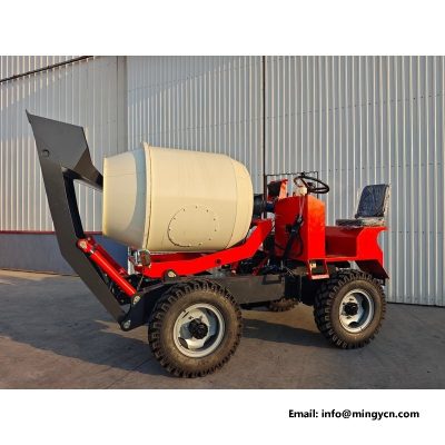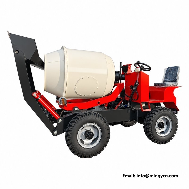
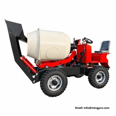
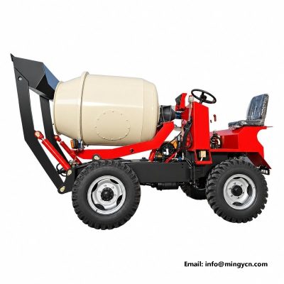
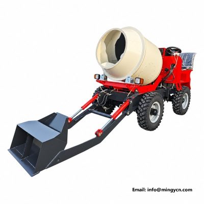
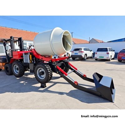
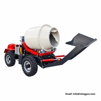
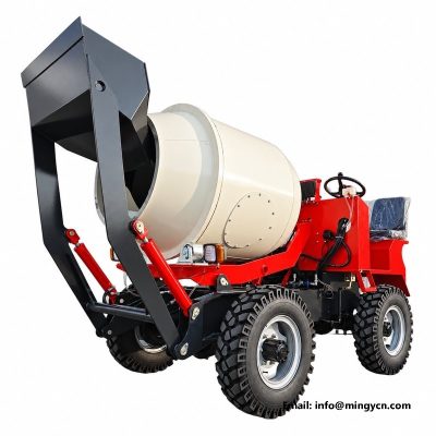
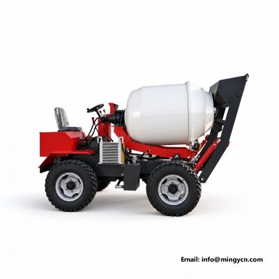
0.8 m3 4WD Self Loading Concrete Mixer Photographed in the Factory Yard with Shovel, Drum and Discharge Chute
A whole machine photographed outdoors tells you what studio photographs cannot. Daylight is honest about paint, panel gaps, weld lines and the way components sit together, and the yard photographs in this page show the 0.8 m³ self loading concrete mixer from the angles a working buyer actually sees: shovel side, drum side, discharge side and the operator’s view. Each photograph is paired with what to look at in it, so the page works as a guided inspection for anyone comparing machines across suppliers before committing to an order.
The sections below walk through the machine area by area in the order an inspection would, from the shovel and drum to the operator platform and the chassis underneath, ending with the short list of things that photographs cannot show and should be asked directly.
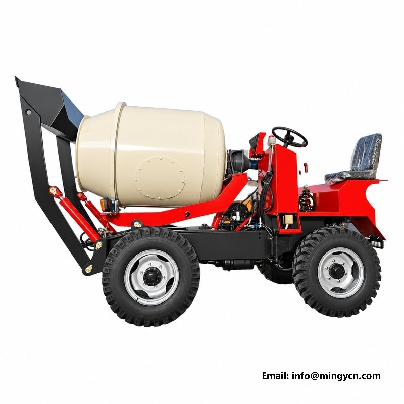
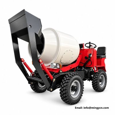
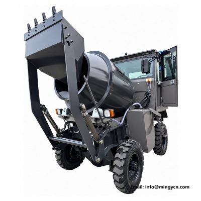
The shovel side carries the working face of the machine. Look at three things in the photograph: the parallelism of the lift arms, which shows in the even gap between arm and cab post on both sides; the bucket cutting edge, straight and unhammered on a new machine; and the routing of the hydraulic hoses to the tilt cylinder, which should follow protected paths with clamps rather than drape across hot or sharp surfaces. Arms that sit unevenly on a new machine hint at assembly jigs that have moved, and hoses clamped properly on delivery are the sign of a line that finishes what it starts. All three checks take a minute each in the photograph and the same minute at a factory gate visit.
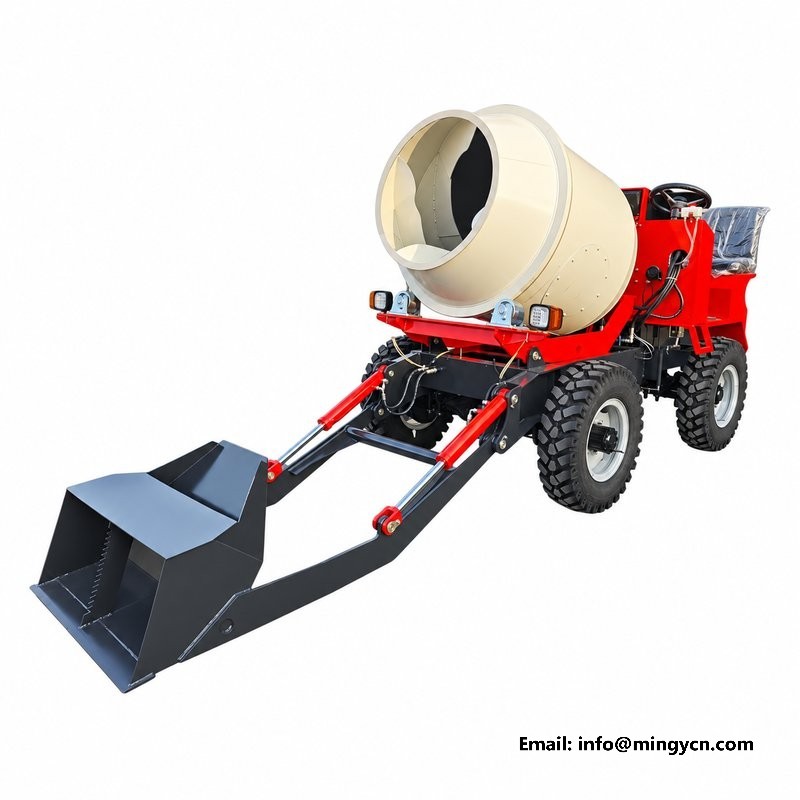
From the drum side, judge the shell by its curve and its finish. A rolled drum shell shows a smooth continuous curve with no flat spots, and the paint carries evenly over the welds that join mouth to shell. The frame that carries the drum should sit square to the chassis, visible in the even gaps around the mounting feet. The water tank sits forward of the drum on this model; its filler is reachable from the ground on the operating side, which matters on sites where the tank is topped up more often than the diesel.
The drum rotation drive is photographed on its own page in this series, so here it is enough to note that the motor and gearbox sit inside the frame profile, protected from the shovel’s working arc.
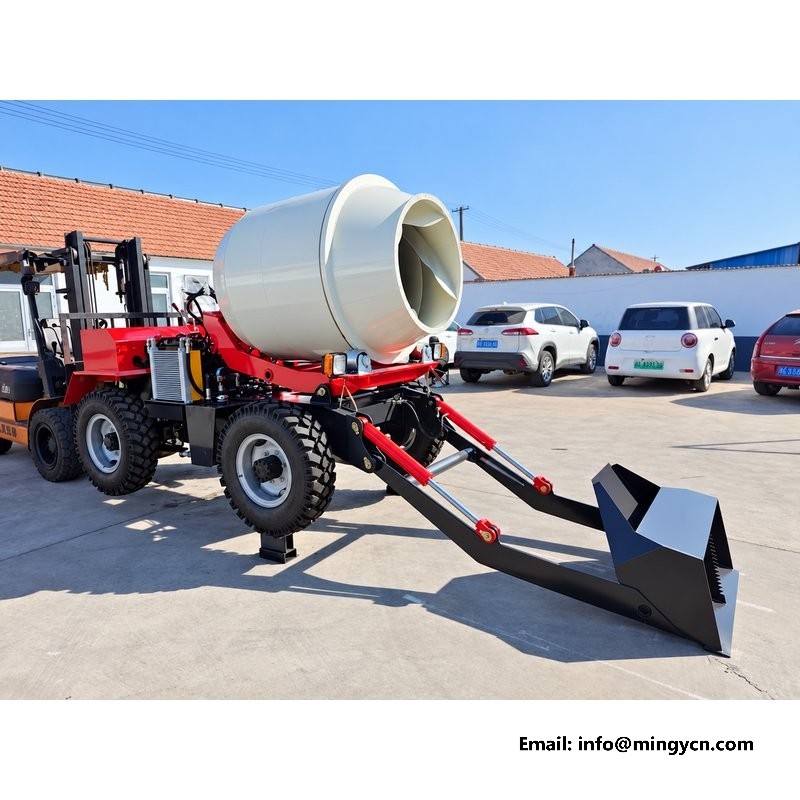
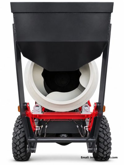
The discharge side is where the machine earns its day, and the photographs show the chute in working position. Watch how the chute swings on its mount and latches for transport; the latch is a wear item on machines that travel between pours, and its design tells you whether the crew will actually use it. The chute lip height over the ground sets what it can pour into: direct to formwork, into a pump hopper, or into buckets on a cart. Buyers pouring into pumps should check the lip height against their hopper in this photograph rather than after delivery, and crews filling carts should confirm the lip clears the container rim with room to spare for the chute swing.
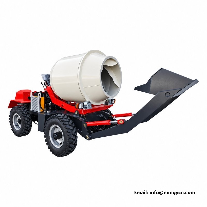
From the platform, an hour of work is judged. The seat should see the shovel teeth at the ground and the drum mouth at the top of its lift without leaning; levers fall within forearm reach; the instruments read at a glance. The photograph shows the layout as delivered: workload on the right hand, drum and water on the left, and the emergency stop where a falling hand finds it. Controls positioned for a test-yard operator rather than a working one show up as stretched reaches in the photograph, and stretched reaches become fatigue on the eighth hour of a pour day.
Visibility is the other half of the platform story. The shovel teeth, the front tyre bottoms and the discharge lip are the three points an operator watches all day, and the photograph lets a buyer check that none of them hides behind a post or a tank. Cab-less platforms also expose the instruments to weather, so the gauge faces sit recessed and shrouded; it is a small detail in the image and a large one in the rain season, when shrouded gauges stay readable and flat ones fog and fade.
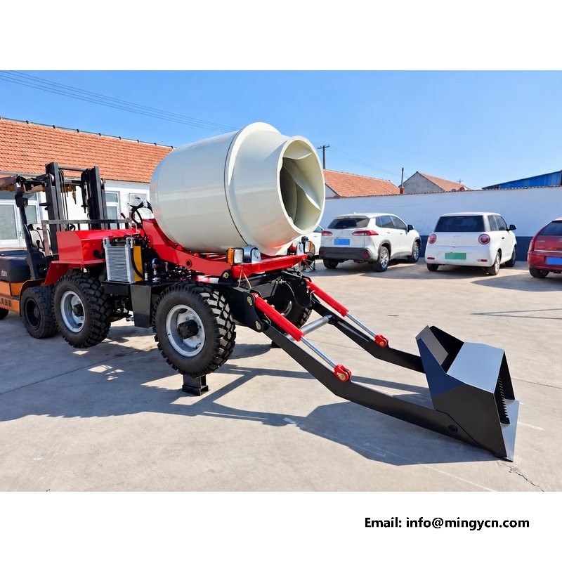
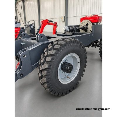
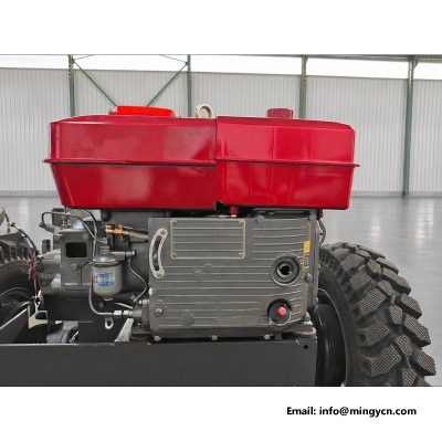
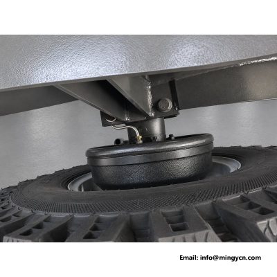
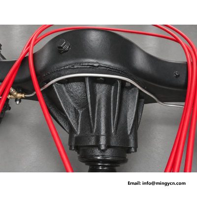
The low photograph across the chassis shows the geometry the component pages describe in detail: axles on their pivots, the driveshaft line, and the paint coverage under the machine. Undercoat quality is easiest to judge here, because the underside is where honest builders and cheap builders part ways. The frame welds visible between the axles should be continuous and dressed, and the hydraulic lines should cross the chassis at clamped, protected points. A torch and two minutes at this angle of a delivery inspection outrank most of the paperwork that accompanies a shipment.
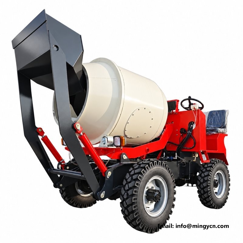
The red finish in these photographs is not only brand. A machine that works among labourers, carts and pump lines wants to be seen, and the colour does that work from the gate of the site. Judge the finish itself in the same photograph: even gloss without orange peel, paint carried into the panel joints, and edges wrapped rather than sprayed past. Paint is also a corrosion system, and its thickness at the chassis is the number that decides how the machine looks after two rain seasons, and how much sanding a repaint in year five will ask of the crew that inherits it. The finish pages in this series cover the paint system in depth; here the daylight photographs make the visual argument.
Daylight also settles the small honesty questions that studio lighting flatters. Sticker placement is square, decals sit on painted surfaces rather than over rough welds, and the machine wears its data plate where it can be read and photographed for the shipping file. None of these details carries load, but together they describe a line that finishes its work, and finishing is the habit a buyer is actually purchasing when two machines list the same specification on paper.
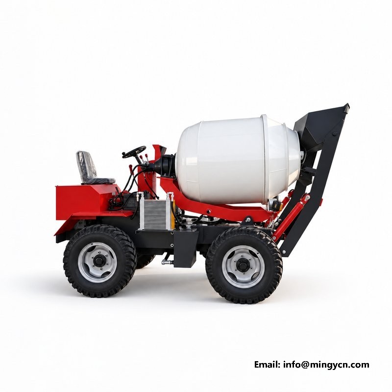
Four things stay invisible no matter how good the camera, and they are worth asking in writing. First, the steel grades and wall thicknesses of drum and frame. Second, the hours rating behind the driveline components. Third, the warranty terms by component group, because a single figure hides what it covers. Fourth, the spare parts commitment for the export market, including delivery times for the wear items. Suppliers answer these questions for machines they expect to keep running abroad; the answer set is itself a quality signal, and it costs one e-mail to collect and one reply to compare across the shortlist.
| Whole-machine reference — 0.8 m³ 4WD self-loading concrete mixer | |
|---|---|
| Configuration | front shovel, rear steer, 4WD, hydraulic drum drive |
| Photographed | production unit in the assembly yard, daylight |
| Finish | safety red polyurethane topcoat over prepared steel |
| Inspection angles | shovel, drum, discharge, platform, underside |
The photographs in this page are of a production machine, not a show model, and individual orders can request the same set of angles for their own unit before shipment.
Photographs only compare fairly when the same questions are put to both machines, and the walk-round above converts easily into a checklist. Send both suppliers the same five angles to photograph, at the same working positions — shovel raised, chute latched, platform clear — and compare like against like. Ask each to photograph the underside with a torch and the welds at the lift arm roots. The supplier who answers with real photographs of a real machine, dated and unretouched, is telling you what your own unit will look like; the supplier who replies with brochure renders is telling you something else entirely. The comparison takes a day of correspondence and answers more than a week of quotation spreadsheets, because steel does not pose, and paint does not hide a rushed weld the way a render can.
Two dimensions from the whole-machine photographs decide whether the machine moves around a site at all: standing height with the drum at rest, and width across the tyres. Sites with covered work, low doorways or narrow compound gates fail machines on these numbers before any quality question is reached. The photographs here include a square-on view from the front that reads the width across the wheel outers, and the side view reads the height with the chute stowed. Buyers with a constrained site should put the gate and door widths in the enquiry, and the factory confirms the machine against them at quotation stage, which is a far cheaper conversation than a container arriving to a gate it cannot pass. Sites change too, so the confirmation covers the route onto the site and not only the gate itself, and it names the person on each side who signs the shipping list against the photographs.
The operating weight of the machine is a working number, not a shipping one: it sets what the shovel can lift, what the tyres carry and what soft ground the axles cross. The yard photographs let a buyer sanity-check the weight claims against visible structure — tube sections, counterweight, drum gauge — because weight that appears on a data sheet but not in the steel has gone somewhere. Where it sits matters as much as what it is: this machine keeps its mass low and between the axles, which is why the platform rides as steadily as the photographs of it working suggest. Machines that carry ballast high on the frame pay for the data-sheet figure in stability, and the difference shows at the first side slope.
A buyer who has walked the machine through this page ends with a short list: the angles checked, the questions photographs cannot answer, and the site numbers that must be confirmed in writing. The factory turns that list into a proforma with the exact specification, the pre-shipment photograph set agreed in advance, and the spare parts box sized to the first season. The whole correspondence usually fits inside a week, and the buyer arrives at shipment day knowing exactly which machine is in the container, because the machine in these photographs is the machine that ships. That certainty, more than any single component, is what the whole-machine walk is for.
Yes. The standard pre-shipment set covers the five angles shown here plus the engine running, and video inspection can be arranged live when a third-party inspector is not practical.
The chute lip height and swing decide whether the machine pours cleanly into a pump hopper or loses mix on the transfer. Checking the geometry against the hopper drawing before ordering avoids a site-made steel adaptation later.
Colour is an order-time choice and larger fleets often standardise on their own. The paint system stays the same whatever the topcoat, and the finish quality in the photographs is what arrives.
The same five angles plus the tyre tread rule shot and the driveline underside. The images become the delivery baseline that every later dispute or wear question is settled against.
Contact MINGYI Machinery for the current 0.8 m³ self loading concrete mixer specification, pre-shipment photograph sets and a formal quotation for your market. E-mail: sales@mingycn.com | LINE (ID): mingyicn
For the components behind these angles, see Reinforced Axle 0.8m3 Self Loading Mixer for Unpaved Sites and the drum, driveline and tyre pages in the mini self loading concrete mixer category.