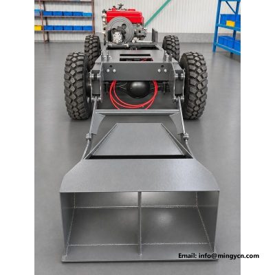
0.8 m3 4WD Self Loading Concrete Mixer Gearbox with Control Levers, Hydraulic Valve Block and Line Routing
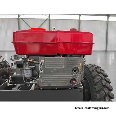
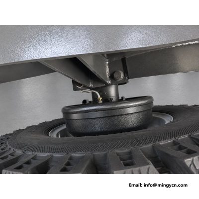
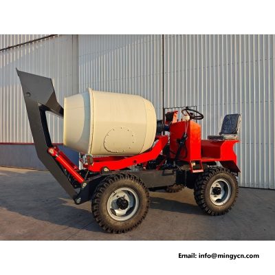
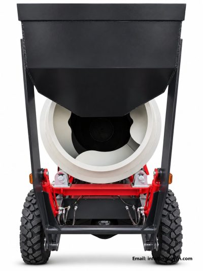
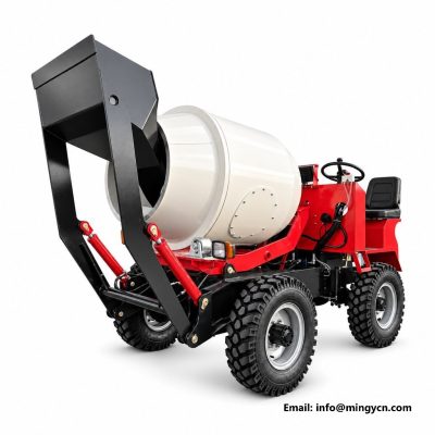
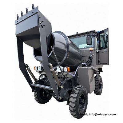
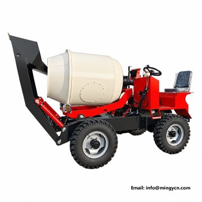
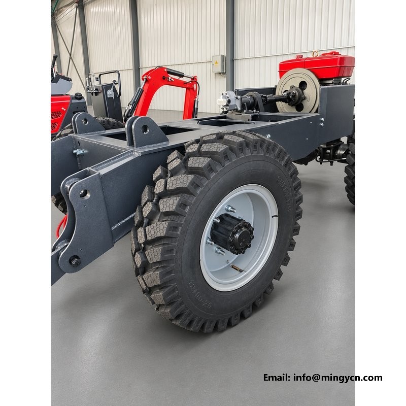
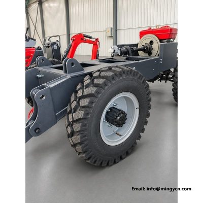
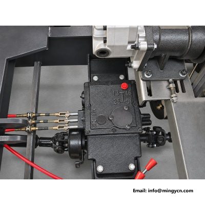
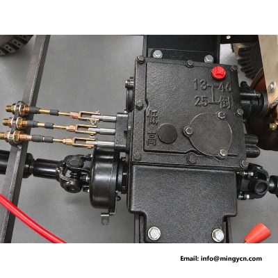
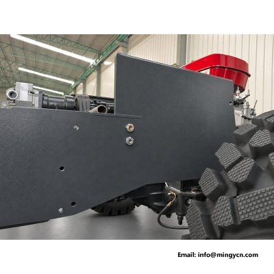
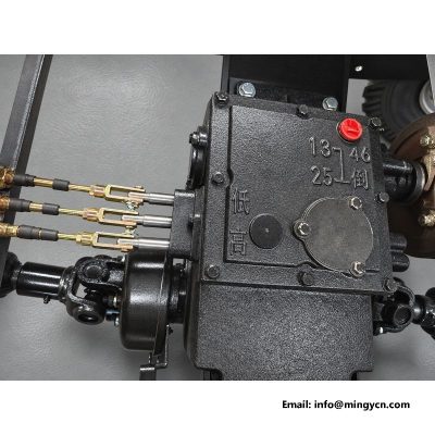
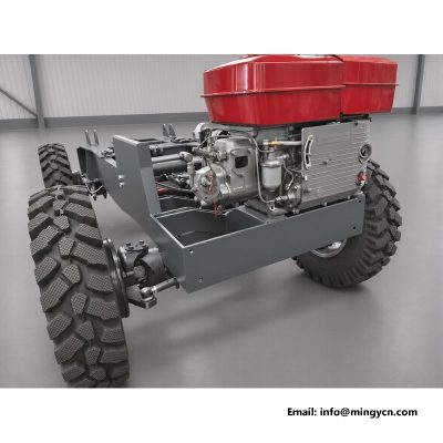
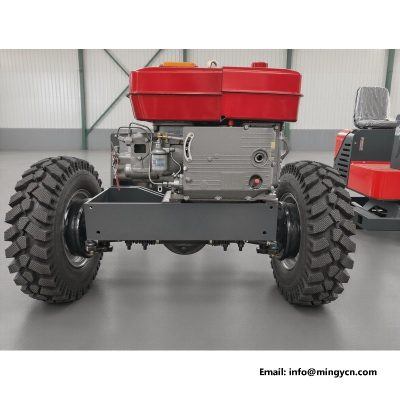
Between the operator’s hands and the wheels of a mixer sits a short list of hardware: a gearbox, a handful of levers, and a valve block with steel lines running out to the drum and the shovel. This is the part of the machine the operator touches all day and the part that decides whether a shift feels controlled or exhausting. The photographs on this page show that hardware on the bare 0.8 m³ four-wheel-drive chassis, before panels hide it, exactly as it is assembled in the works.
The sections below cover the gearbox and its ranges, how the levers are laid out and why, where the hydraulic valve block sits, how the lines are routed and clamped, and what all of this means for daily operation and maintenance.
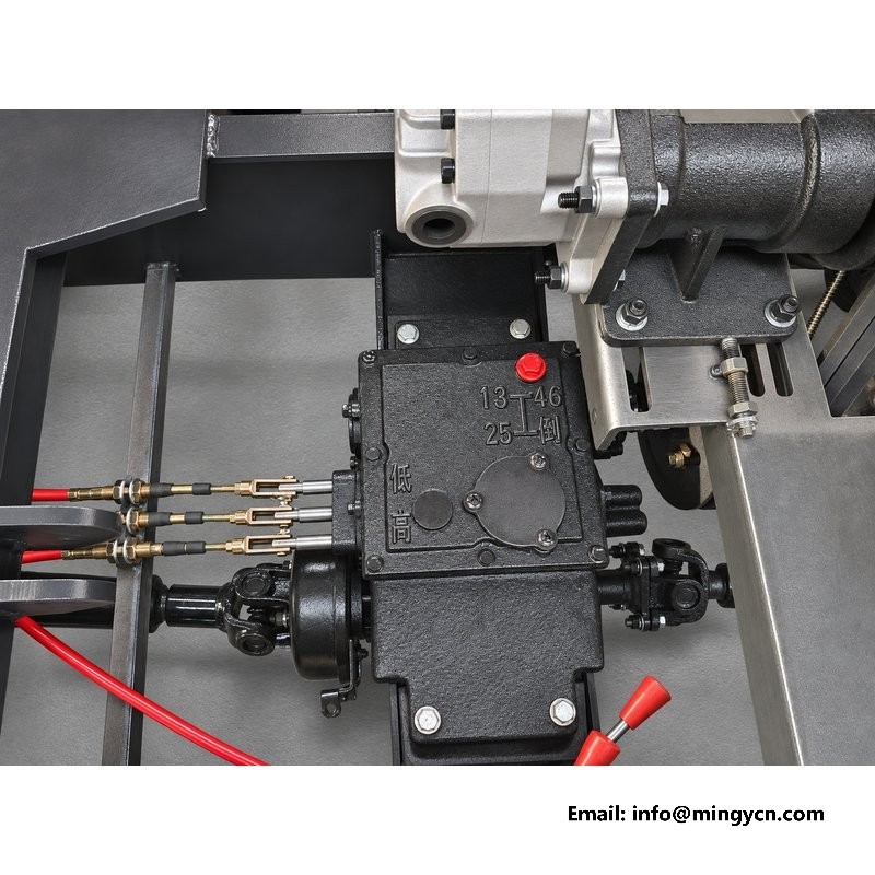
The transmission is a constant-mesh gearbox with three forward ranges, one reverse, and a separate travel gear for moving between pours. The range structure matters more on a mixer than the raw count suggests. First range is a working gear: loading the shovel, creeping to the drum mouth, positioning beside formwork. Second is the transfer gear for moving around a site with a part-full drum. Third and the travel gear exist for the road legs between sites, where the machine runs light and the operator wants the distance covered rather than the torque preserved.
Constant-mesh gearing means the dogs engage without the whole gearset stopping, which makes range changes forgiving even for operators who arrive from agricultural machines with rougher gearboxes. It also means fewer broken teeth, which is the failure that strands machines in the field.
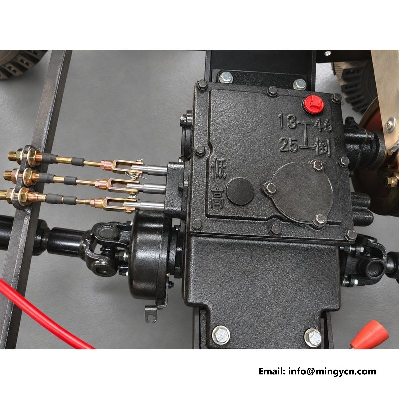
Every lever on this chassis clusters within reach of the operator position without a seat belt stretch: range selection, drum rotation, shovel lift and the throttle. The layout follows one rule learned from years of watching operators work: the hand that steers keeps steering, and the other hand never has to cross the body to reach a function. Drum control sits nearest the operator because it is used most often; range selection is the longest throw but the least frequent.
On the photographs the lever bosses are machined into the gearbox housing itself rather than bolted on as a separate tower. Fewer joints mean less free play developing at the base of each lever, which is where cheap builds get their characteristic rattle in the first year.
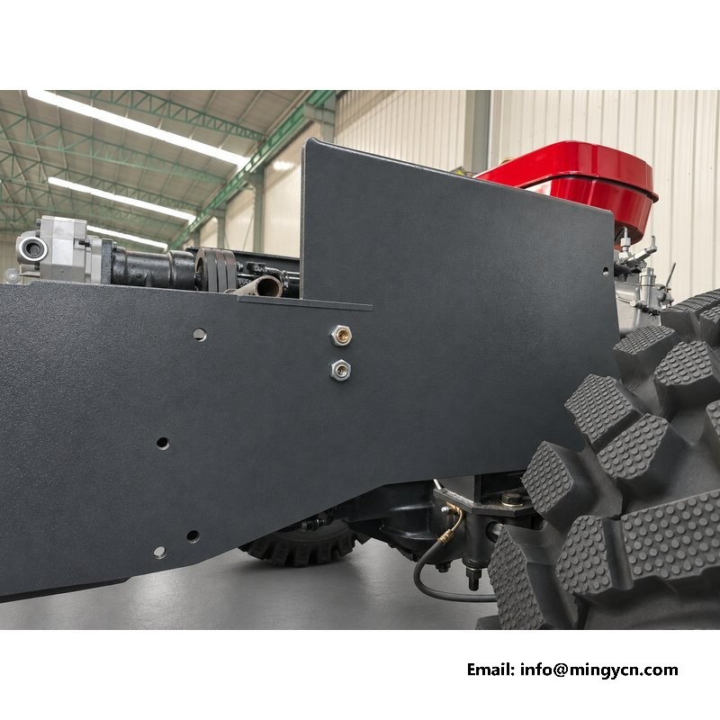
One pump feeds everything hydraulic on this machine: the drum motor, the shovel cylinders and the steering. The valve block in the photograph splits that supply and enforces a priority order that is worth understanding. Steering has first claim, the drum holds second, and the shovel takes what remains. The reasoning is safety: an operator must never lose steering because the shovel was digging hard at the same moment.
The block is mounted high on the frame where it stays out of the mud, and every port is reachable with a spanner from above. Buyers comparing machines should look at this area in photographs: a valve block buried behind panels means every future adjustment starts with removing half the machine.
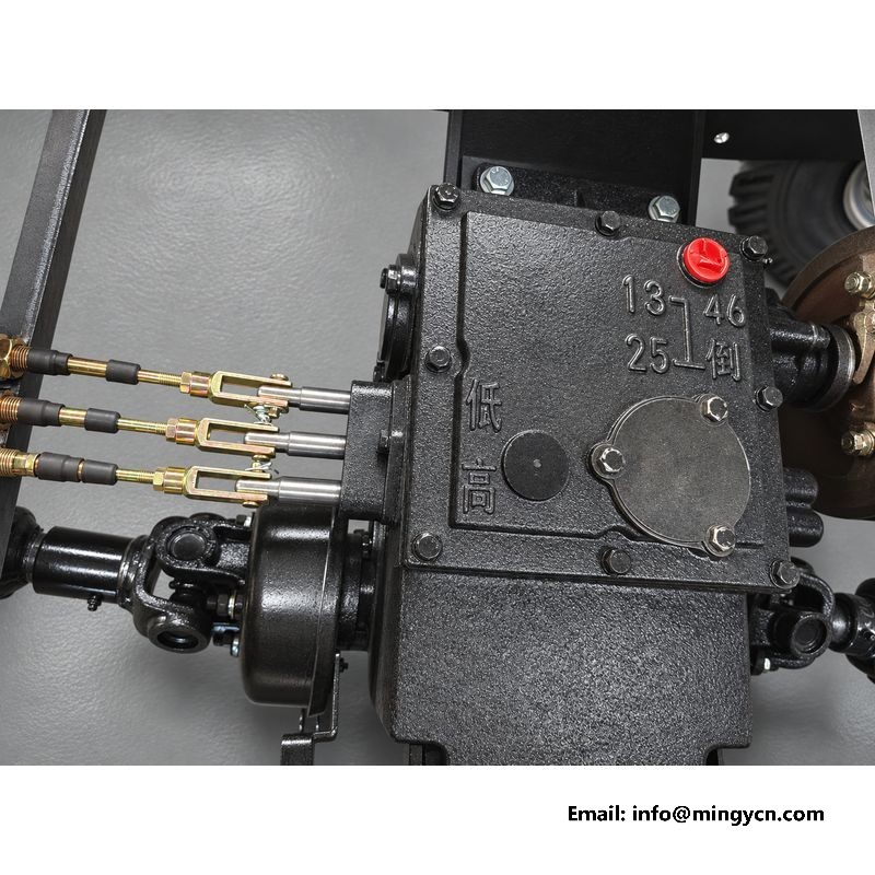
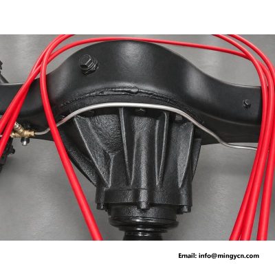
Hydraulic lines fail from rubbing, not from pressure, and rubbing starts where a line is free to move. On this chassis every run is clamped to the frame at short intervals, passes through grommets where it crosses an edge, and keeps away from the exhaust side. The steel sections carry the fixed runs; flexible hose appears only where movement demands it, at the shovel cylinders and the drum motor swivel.
The routing also follows a service logic: any single line can be replaced without removing its neighbours. That sounds obvious until a machine arrives where three lines share one clamp stack and a two-hour job becomes a day.
Lever feel is a quality signal that photographs cannot carry, so it is worth describing. The range lever moves through defined gates with a firm notch at each position and no slop in the middle. The drum lever is lighter, proportional in the sense that drum speed follows lever travel, and it returns to neutral positively. The shovel lever carries the most load and therefore the most hydraulic feedback; a small bounce in the lever when a loaded scoop lands is normal, a continued drift after release is not, and it points at a cylinder seal rather than at the lever.
At handover the crew should cycle every lever twenty times through its full travel. Stiffness that eases with use is assembly grease; stiffness that stays is a bent lever or a pinched line, and it is easier to fix before the container is signed for.
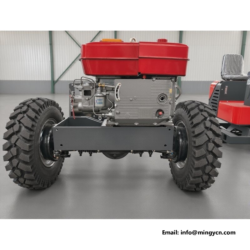
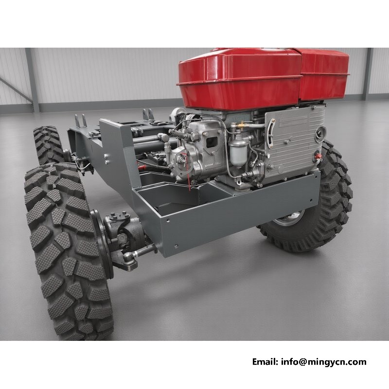
The gearbox mounts on a machined pad between the frame rails, aligned with the engine coupling and both axle driveshafts. Alignment matters here more than almost anywhere else: a half-degree error at the coupling shows up as vibration in the floor plate and wears the universal crosses at twice the normal rate. The factory aligns the pad before welding and re-checks after welding, which is the only order of operations that keeps it true.
Around it, the frame leaves service windows: the drain plugs of the gearbox face outward and downward, the filler reaches without removing the floor plate, and the linkage adjustments sit in open air. Nothing about the layout requires an engine hoist for a routine oil change.
| Transmission and hydraulics reference — 0.8 m³ 4WD mixer | |
|---|---|
| Gears | 3 forward / 1 reverse + travel gear |
| Transmission | 4WD, constant mesh |
| Drum drive | hydraulic motor with planetary reduction |
| Steering | hydraulic power steering, priority valve |
| Shovel | hydraulic lift and tilt cylinders |
| Maximum travel speed | 24 km/h |
| Engine | single-cylinder diesel / 25 hp class |
Oil capacities and grades for the gearbox and hydraulic tank are listed in the manual that travels with the machine; both take common agricultural grades available in any district town.
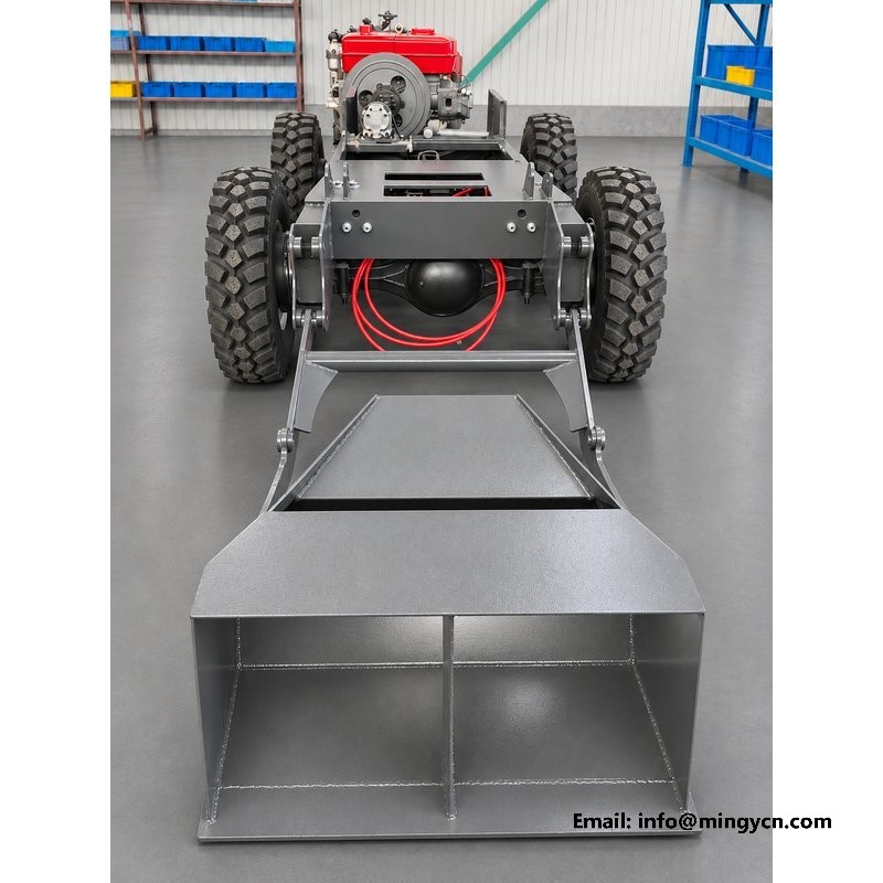
The daily round at this end of the machine is thirty seconds: a glance along the hydraulic lines for fresh wet spots, a feel of each lever for its normal weight, and a look under the valve block for drips. The weekly round adds two greasing points on the linkage and a check of the gearbox oil level through the level plug. Monthly, wipe each line where it passes a clamp and look for the shiny wear patch that precedes a weep.
Hydraulic oil tells its own story if it is asked. Milky oil means water, burnt smell means the cooling has been neglected, and glitter means a pump is eating itself, all visible on the dipstick or filler cap a month before the machine complains.
Three adjustments cover ninety per cent of the work in this area. Range linkage: when the lever starts popping out of gear on bumps, the rod ends take up the slack in two lock-nuts. Drum lever friction: a knurled nut at the lever base restores the drag that holds a mid-travel position. Relief pressure: checked with a gauge at the test port, adjusted only with the manual open, and only if drum speed has genuinely fallen with the oil hot.
Everything else in this area is replacement rather than adjustment, and the parts are common items that any agricultural dealer can supply.
The gear pattern on this gearbox will feel immediately familiar to anyone who has driven a walking tractor or a small agricultural loader, and that is deliberate. The export markets for this machine, from Southeast Asia to Central Asia, are full of operators whose first machine was something agricultural. Keeping the range pattern, the lever throws and even the direction of travel-gear engagement consistent with what they already know cuts training to a demonstration rather than a course, and it removes a whole class of early-life gearbox abuse caused by hunting for the right gate.
The same logic runs through the drum lever, which rotates forward for mixing and reverses for discharge in the same sense regardless of which side of the machine the operator stands on. Small decisions like these never appear on a specification sheet, and they are exactly what an operator notices in the first hour.
Hydraulic oil has a working window, and this machine spends its life at the edges of it. In hot-season work the drum motor and the relief valve generate the heat, and the cooler on the tank keeps the oil in range provided its fins are cleaned daily in dusty conditions. Overheating announces itself as drum speed that fades after an hour of continuous mixing, and it is solved by cleaning, never by turning the relief pressure up.
In cold mornings the same oil is stiff, and the correct routine is to run the drum empty at slow speed for a few minutes before loading. Forcing a cold system to full pressure works the seals hard and is the usual origin of the weeps that appear in a machine second winter. Where winters are serious, the oil grade can be specified for low temperature at order time.
Three options are worth considering at order time rather than after delivery. Electric start on the engine pairs well with machines that start and stop many times a day. A road-legal lighting kit matters where the machine will travel between sites on public roads. And for fleets, specifying one common oil grade across the gearbox and hydraulic system on every unit simplifies site stock to a single drum of oil. All three are cheap at the factory and awkward afterwards.
Ten minutes at delivery covers this area. Start the engine, cycle every lever through its full travel and feel for smooth gates. Engage each range with the clutch fully pressed and confirm none grinds. Watch the drum rotate both ways at slow speed. Raise and lower the shovel and check the cylinders hold position over a minute without drifting. Finally, look underneath at every hydraulic connection for a dry film rather than a wet one. Any finding goes on the delivery note with a photograph before the container is signed.
Yes, usually within a morning. The range lever works like any agricultural gearbox, the drum lever is one function doing one thing, and the shovel lever behaves like a small loader. The priority hydraulic layout means mistakes in sequencing cost time, not safety.
In order of frequency: hydraulic line rubbing points where a clamp was knocked loose, range linkage rod ends, and lever boots torn by boots and sun. All are field-replaceable in minutes. Gearbox internals on this pattern very rarely fail if the oil is changed on schedule.
No. The hydraulic tank is separate from the engine sump, with its own filter and cooler. The two are often confused on first service because they sit close together; the fillers are labelled and the manual shows both clearly.
Drum speed follows the lever and the engine throttle, so the operator already has continuous control. A fixed maximum is set by the relief valve; changing it is a factory conversation, since drum speed, mixer design and motor rating are matched.
Contact MINGYI Machinery for the current 0.8 m³ self loading concrete mixer specification, transmission details and a formal quotation for your market. E-mail: sales@mingycn.com | LINE (ID): mingyicn
For the hydraulic drum drive itself, see the mini self loading concrete mixer category hydraulic drive page, and for the chassis these levers mount on, read Reinforced Axle 0.8m3 Self Loading Mixer for Unpaved Sites. Buying notes sit in the self loading mixer guides.