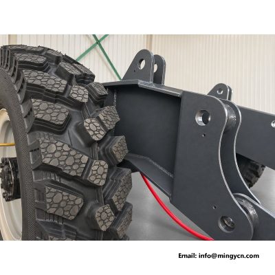
0.8 m3 4WD Self Loading Concrete Mixer with Heavy Hub Fixings, Enclosed Brake Drums and Tie Rod Steering
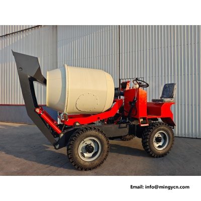
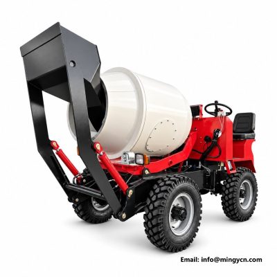
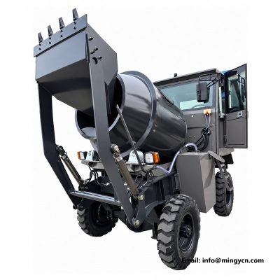
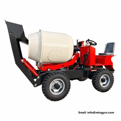
A mixer that will not stop is not a mixer, it is a hazard with a drum on top. The 0.8 m³ four-wheel-drive machine carries one and a half tonnes of concrete at up to 24 km/h, often downhill toward a pour, on ground that is rarely kind to brakes. The photographs on this page show the wheel-end hardware that does the stopping and the steering: heavy hub fixings, enclosed brake drums, the stub axles they run on and the tie-rod links that keep all four wheels pointing the same way.
The sections below walk through each part in turn, explain the design choices behind them, and finish with the adjustment routine, the handover checks and the specification table.
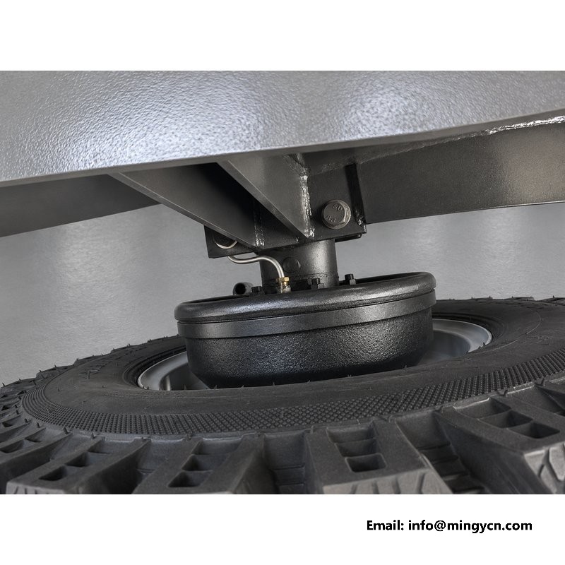
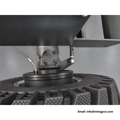
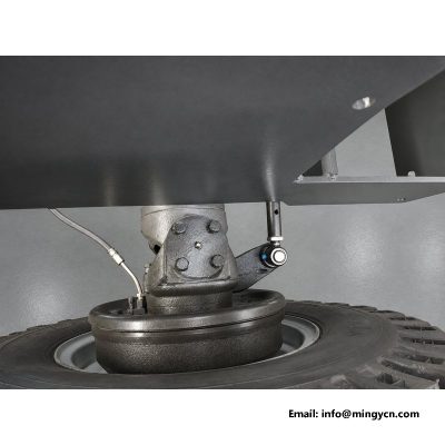
The first image shows the complete wheel-end assembly with the wheel removed: the cast brake drum sitting over the hub, the stub axle carrying both on tapered bearings, and the backing plate that seals the working parts behind them. Everything the brake needs is inside that drum, and everything the wheel needs rides on those bearings. It is a deliberately conventional layout, borrowed from light trucks, because conventional means every rural workshop already knows how to service it.
Conventional also means inspectable. Pull the drum and the condition of shoes, springs, cylinder and bearings is in plain sight, with no sealed caliper to guess about and no special tool beyond a brake spring pliers.
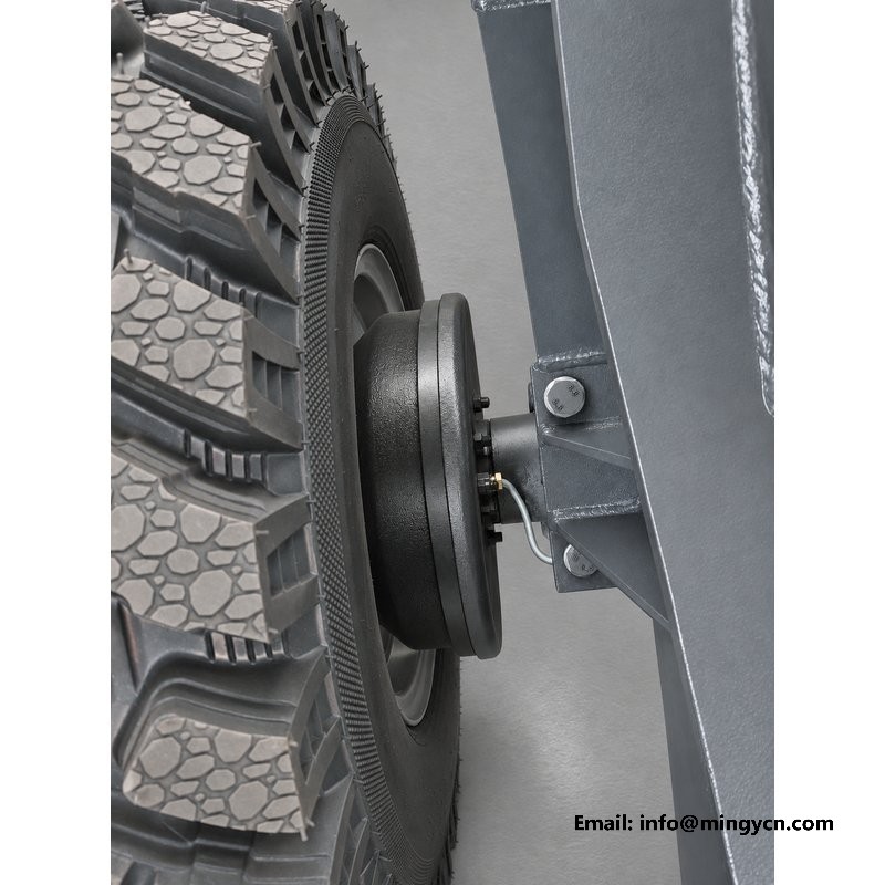
Disc brakes stop better in the dry, but a concrete site is not the dry. Sand, mix spillage and clay dust eat exposed discs and pads alive, and a mixer spends its whole life spraying exactly those materials while turning and discharging. Drum brakes seal their shoes and springs inside the casting, and the friction surface is only exposed when the wheel is off. On site machinery this is the older technology that simply survives longer between services.
The drum on this build is a full cast iron ring, not a stamped carrier, so it also acts as a structural part of the wheel end and shrugs off the knocks that come from mounting tyres in the field.
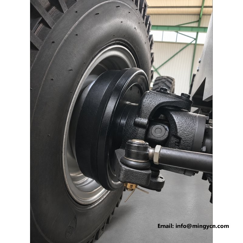
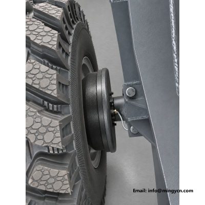
Each wheel rides on a pair of tapered roller bearings on a forged stub axle. Tapered bearings carry side load well, which matters when the machine works across slopes and the tyre is constantly leaning on its hub. They are also adjustable: end float is set with the castellated nut and split pin at the axle end, checked by rocking the wheel at the twelve and six o’clock positions.
The adjustment takes minutes and is the single most neglected job on small site machinery. A loose bearing lets the drum rub the backing plate and lets water past the seal; an over-tight one runs hot and wrecks the grease. Both failures are cheap to prevent and expensive to discover mid-season.
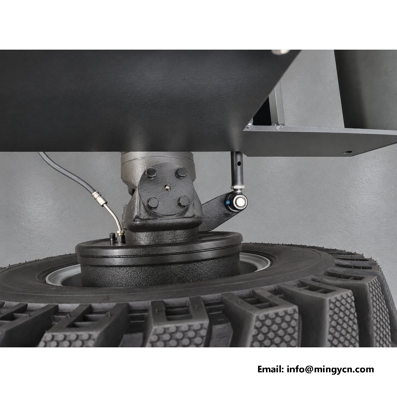
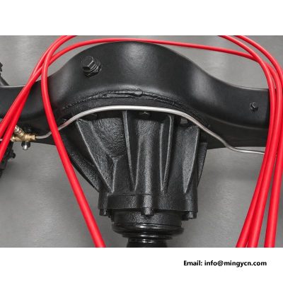
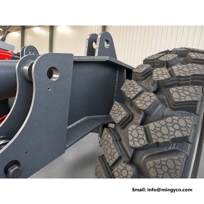
Behind the wheel end sits the pivot that lets the rear axle swing. The photograph shows the pivot housing and the linkage that passes through it. Layout matters here: the brake lines and the rod linkage are routed so the axle can articulate through its full travel without stretching anything, and the pivot bush is greased from a single point reachable from above the frame.
When this pivot dries out, the symptoms arrive sideways: steering pulls to one side on rutted ground and the rear tyres wear in steps. Greasing it is a two-minute weekly job, and the grease nipple is placed where a grease gun actually reaches, which on some machines is more of a design achievement than it sounds.
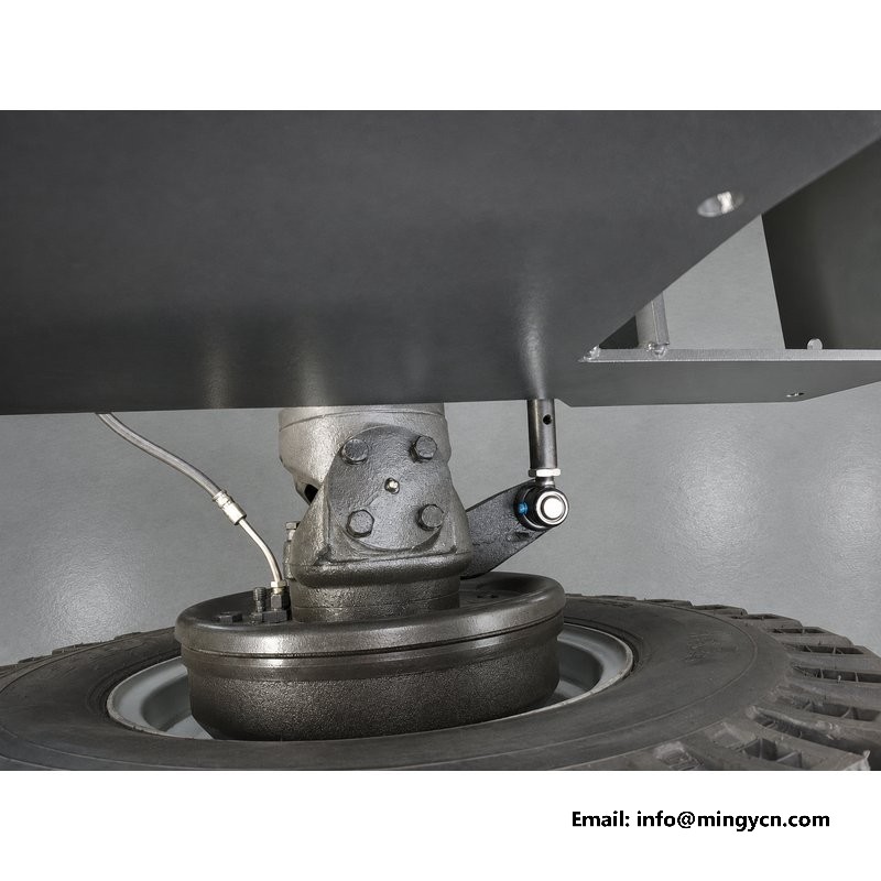
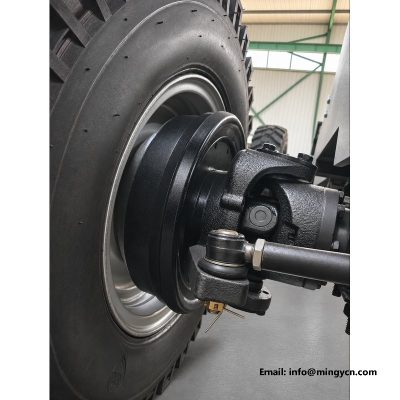
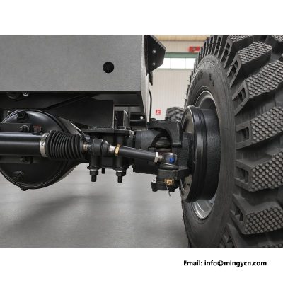
Steering on the steered axle runs through a tie rod with ball joints at each end, set so both wheels track parallel through the full 28 degrees of steering angle. The ball joints are the wear item, and they tell you before they fail: a dry joint knocks over bumps, a worn one lets the steering wheel develop free play that grows week by week. Replacement is a split-pin and a castellated nut, and the alignment is restored with a tape measure and the lock nuts on the rod itself.
Hydraulic power steering assists the effort, but the geometry is entirely mechanical, which is why it can be checked and set anywhere with a tape measure and a spanner rather than a laptop.
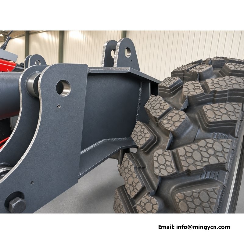
On the driven axles the drive arrives through a short shaft with a universal joint at the hub end, visible in the photograph entering the hub flange. Keeping this joint greased and its dust cap in place is the whole of its maintenance. When a joint does wear out, the symptom is a clunk on direction changes, and the repair is a new cross and bearing kit fitted in the frame, not a new axle.
The four-wheel-drive system sends torque to both axles, so there are two of everything: two driveshafts, two differentials and two sets of hubs doing this work. It is one reason the wheel-end check at handover takes a little longer than on a two-wheel-drive machine, and one reason it matters more.
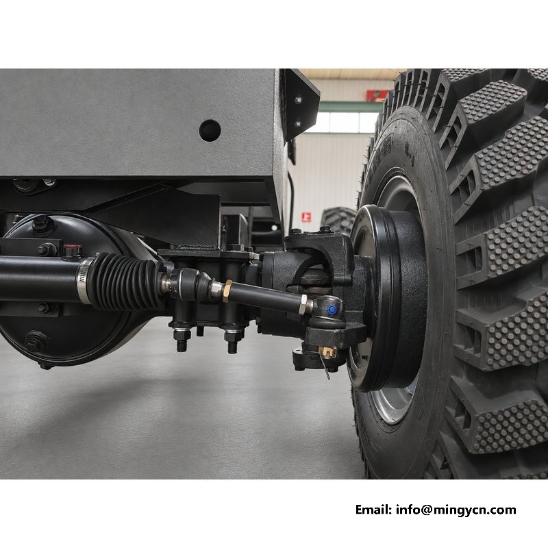
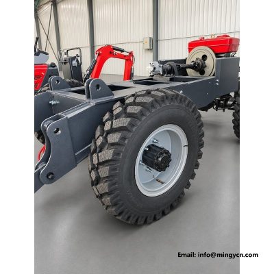
The deep-lug tyres fitted here do part of the braking themselves. A tall, flexible lug grips loose ground where a highway pattern would slide, and a tread block close to 30 mm thick keeps its shape under the heat a drum brake pushes into the tyre on a long downhill. Wheel balance matters too: an unbalanced tyre shakes the steering at travel speed and fatigues the tie-rod ends for no reason. Static balancing on the rim is a five-minute job at any tyre shop and belongs in the commissioning routine after every tyre change.
| Wheel-end reference — 0.8 m³ 4WD self-loading mixer | |
|---|---|
| Brakes | hydraulic drum brakes, all four wheels |
| Brake drum | cast iron, enclosed shoe set |
| Hub bearings | tapered roller, adjustable end float |
| Steering | hydraulic power assist, tie-rod linkage, 28° angle |
| Turning dimension (outer tyre) | 2,464 mm |
| Tyres | 8.25-16 front, 7.50-16 rear, deep lug |
| Maximum travel speed | 24 km/h |
| Rated load | 1,500 kg |
Brake specification is the same at every wheel, front and rear, which keeps the spare shoe and cylinder stock to one set of part numbers.
Drum brakes self-adjust in principle and never quite manage it in the dust. The working routine is: jack the wheel clear, spin it by hand, adjust the star wheel until the shoe just drags, then back off until it spins free, and repeat until the pedal height comes up. Do all four wheels and the pedal firms noticeably. On a machine doing daily work this belongs in the weekly round; on a machine doing seasonal work, at the start of every season without exception.
Shoe replacement follows the same access: drum off, springs off, shoes off, cylinders inspected for weeping at the bleeder and boot, then reassemble and bleed. Every agricultural dealer stocks the parts, and the job needs no more than a stand, a hammer and an afternoon.
Four checks at delivery, ten minutes total. Rock each wheel top to bottom for bearing float. Spin each wheel and listen for graunching that suggests a dragging shoe or a dry bearing. Turn the steering lock to lock and watch the tie-rod ball joints for looseness in their seats. Then drive the machine a short distance and brake firmly twice: the pull should be straight and the pedal solid. Write any finding on the delivery note before signing for the container.
One more observation belongs in the handover notes. On a four-wheel-drive machine the front and rear wheels turn at slightly different rates whenever the machine steers, because a small mixer of this class uses a simple on-demand front drive rather than a full differential splitter between axles. The practical consequence is benign: a little driveline wind-up on hard, dry turns, and tyres that scrub slightly on concrete. It is not a fault. Operators coming from road vehicles should simply be told that a faint resistance on full lock, on dry paving, is the drivetrain doing what this layout does.
The wheel-end spares that earn their place in the parts box are one shoe set per axle, one wheel cylinder, a bearing and seal kit for one hub, two tie-rod ends, and the castellated nuts and split pins that go with them. None of it is expensive, all of it is standard, and together it covers the failures that would otherwise park the machine at the far end of a site waiting for a part to travel.
Drum brakes behave differently from discs in one respect that matters on site: they recover from water and mud faster than an exposed disc, because the shoe runs on the inside face of a casting that sheds material outward. A disc sandwiched in grit grinds that grit between pad and steel until both are scored. This is the same reasoning that keeps drums on agricultural trailers and most site machinery, and it is why the enclosed drum here is a considered choice rather than a cost saving.
The design does have one discipline attached: after a season of pressure washing or heavy rain, the first few brake applications do less than the operator expects while water cooks out of the shoes. Crews should know this and test the pedal after washing, the same way truck drivers do, rather than discovering it at the top of a ramp.
The machine tops out at 24 km/h, which sounds modest until a full drum is aboard. Braking distance on firm ground from that speed is short with all four drums working; on wet clay it is roughly double, and on a downgrade it doubles again. The operating habit that follows is simple and worth writing into every handover: slow before the slope, keep the shovel low when loaded, and use the gears on descents the way the manual describes rather than riding the pedal all the way down. Drum brakes fade when held; they are at their best when applied firmly and briefly.
Because the working environment punishes exposed discs. Sealed drums keep the friction parts clean, last longer between services on site material, and can be serviced by any rural workshop. The stopping power on a 1.5-tonne machine at 24 km/h is fully adequate with all four drums working.
Annually, or every 1,000 hours, whichever comes first. In wet season conditions check the end float monthly; a quarter turn of the adjuster nut usually restores it without a full repack.
Three usual suspects in order: a dry rear axle pivot bush, worn tie-rod ball ends, and tyre pressures set unevenly side to side. All three are checked in minutes, and none of them is a reason to blame the steering valve first.
The layout is light-truck standard but the specific shoe and drum dimensions are the factory’s. Order brake parts from the factory parts list rather than matching by eye at a market stall, and keep one set on the shelf as suggested above.
Contact MINGYI Machinery for the current 0.8 m³ self loading concrete mixer specification, the wheel-end parts list and a formal quotation for your market. E-mail: sales@mingycn.com | LINE (ID): mingyicn
For the tyres that sit on these hubs, see Wheeled Diesel Self-Loading Mixer: Tyres and Traction, and for the axle structures behind them, the reinforced axle page Reinforced Axle 0.8m3 Self Loading Mixer for Unpaved Sites. The full range sits in the mini self loading concrete mixer category.