Hydraulic Drive System of the 0.8 m3 Self Loading Concrete Mixer with Orbit Motor, Reduction Gearbox and Steel Lines
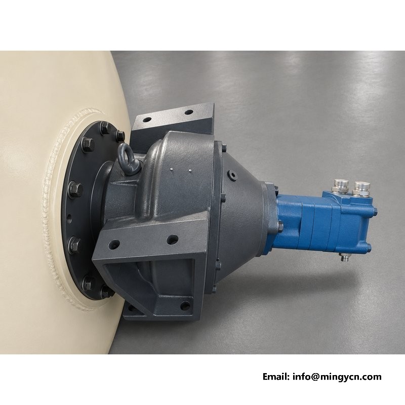
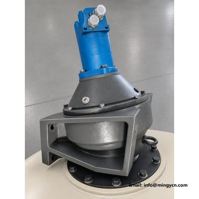
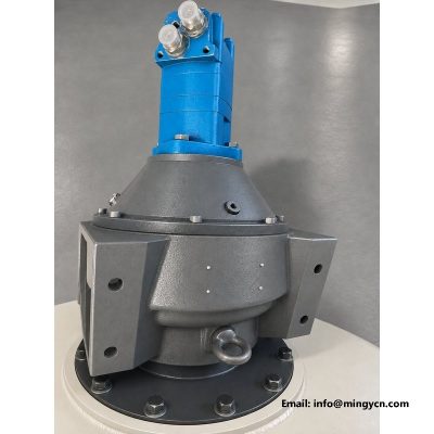
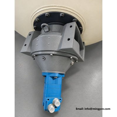
Ask a mixer operator what makes one machine pleasant and another one tiresome, and the answer is usually the drum drive. A chain whines and needs tensioning; a belt slips when the mix is stiff; a direct hydraulic motor with a planetary gearbox just turns, holds its speed under load, and reverses the moment the lever asks. The photographs on this page show that drive taken off the 0.8 m³ machine and photographed properly: the orbit motor, the two-stage reduction gearbox, the splined coupling between them, and the steel lines that feed the pair.
The sections below explain how the drive works, why each stage exists, how the fuel system that powers the pump sits alongside it, and what maintenance this elegant corner of the machine actually asks for, which is less than any buyer expects.
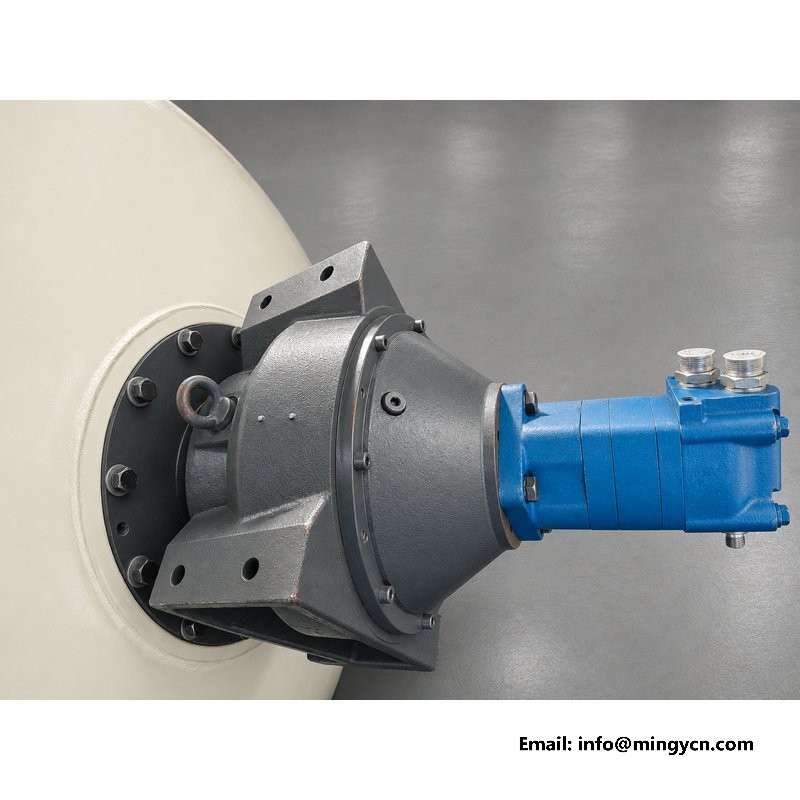
Turning a full drum needs slow rotation and enormous torque. The hydraulic system produces exactly the opposite naturally: fast oil flow at moderate pressure. Three stages convert one into the other. The pump on the engine makes the flow. The orbit motor converts flow into fast, low-torque rotation. The planetary gearbox divides the speed and multiplies the torque in two planetary stages before the drum shaft ever feels it. Each stage is a mature, mass-produced component, which is the quiet advantage of the layout: replacements are commodity parts, not bespoke castings.
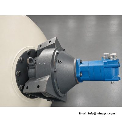
The assembly in the photographs bolts together as a unit, motor to gearbox to drum, with the splined coupling hidden inside the flange between the first two. Nothing in the chain needs shimming or timing; alignment is carried by the machined spigots.
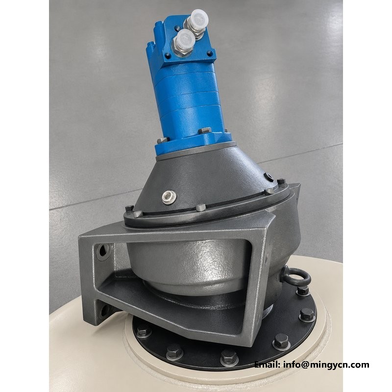
Orbit motors, of the geroler type common on agricultural machinery, have three properties a drum cares about. They produce full torque at very low speed, which is what a stiff mix demands at start-up. They tolerate the dirt and heat of a construction site behind simple shaft seals. And they hold their efficiency across the whole speed range, so drum speed follows the lever smoothly instead of stepping. Spool-valve motors of this type run happily on the same oil grade as the rest of the machine, which keeps the site stock simple.
Their weakness is contamination, and the answer on this build is a full-flow filter on the return line plus a magnetic drain plug in the tank. Two cheap parts that decide the life of the motor.
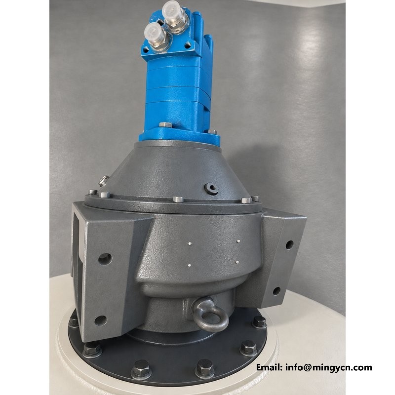
The gearbox carries two planetary stages in a compact cast housing. Planetary stages are the right architecture for a drum because the load splits across three planet gears at once, so the teeth never see the full torque alone. The housing on this build is the industry-standard pattern used across concrete mixers worldwide, which means seal kits and planet sets are stocked by dealers on every continent rather than only by the factory.
The oil sump in the gearbox is sized for the whole service interval, with a level plug and a magnetic drain. Checking it is an annual job and the level plug is placed so the check can be done with the drum fitted, from the rear of the machine, without removing anything.
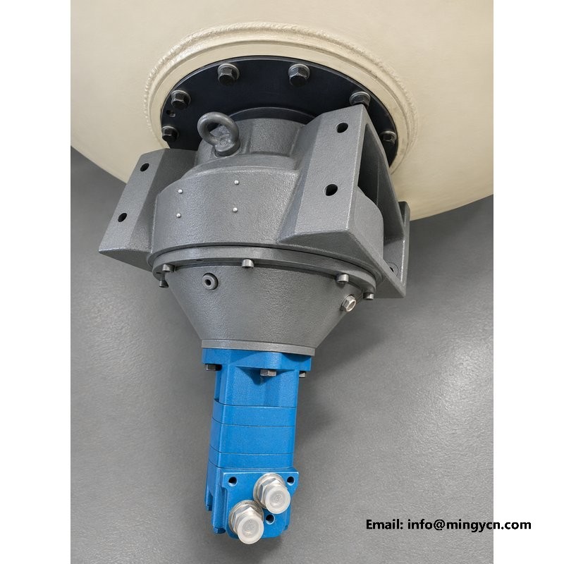
Between motor and gearbox sits a splined coupling with a grease pocket behind it. This joint carries the entire drum torque, and its only maintenance is a grease nipple reach at the annual service. A dry spline wears into slack that shows up as a knock each time the drum changes direction, a sound operators learn to dislike. Ten seconds with a grease gun per year is the whole prevention.
The coupling also acts as the drive’s fuse. If the drum is ever jammed by set concrete, the spline shears or the motor cases fail before the drum shell or the chassis saddle take damage, and the repair is a coupling rather than a drum.
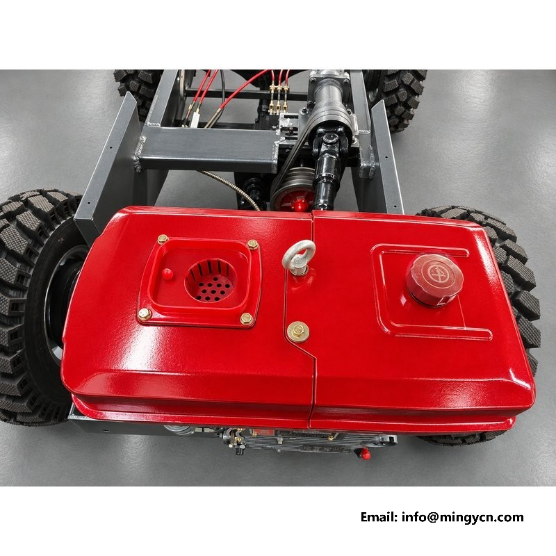
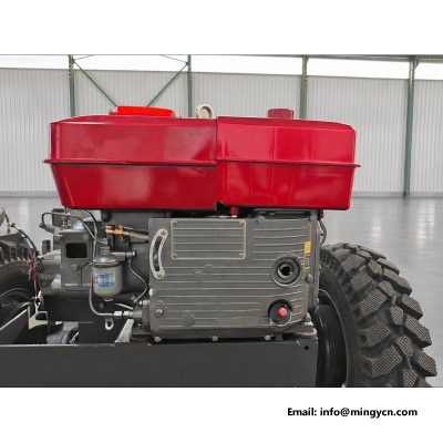
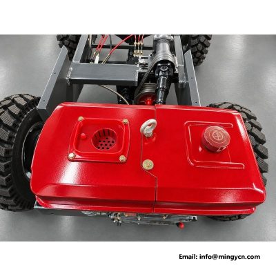
The red tank above the engine feeds the pump through a suction strainer and receives the return flow through the cooler and the full-flow filter. Its top plate carries the filler, the level gauge and the drain, all reachable from the operator platform. Tank size is chosen for heat rather than volume: on a machine this size the oil needs surface area to shed the heat the drum circuit makes during long mixing runs, and the finned cooler behind the tank does that work.
The gauge matters daily. Oil level that falls slowly points at a weeping line; level that rises points at water getting in. Both are found on the gauge weeks before they are found by failure.
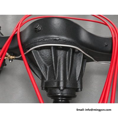
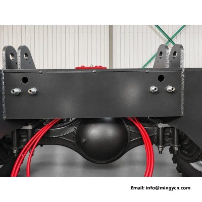
From the pump to the valve block to the motor, the fixed runs are hard steel line clamped along the frame, with flexible hose only at the drum swivel and the shovel cylinders. Steel line costs more to bend at the factory and lasts years longer on the machine, because it cannot rub through on an edge the way an unprotected hose does. Every fitting on this build is a standard metric flare, so replacements come from any hydraulic shop in any town.
The photograph shows the other detail worth copying: lines leave the pump in a bundle, then separate and clamp individually, so a single line can be opened without disturbing its neighbours.
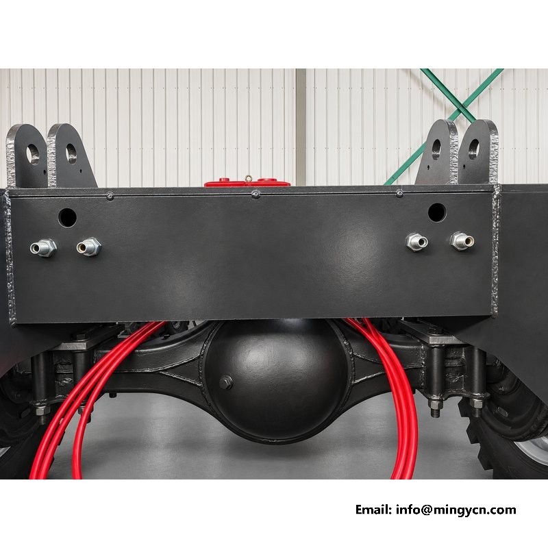
Loaded behaviour is where this drive earns its keep. As the mix stiffens, the drum slows slightly and the pressure rises; the relief valve then holds the maximum and the drum keeps its floor speed. The operator feels none of this except through the lever. There is no belt to slip, no chain to jump, no clutch to smell. Reversing for discharge is instant, because the motor simply runs the other way through the same gears.
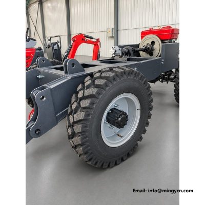
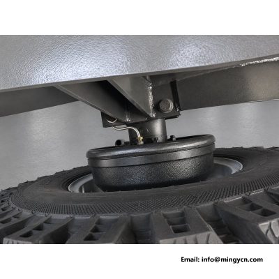
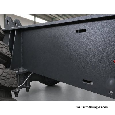
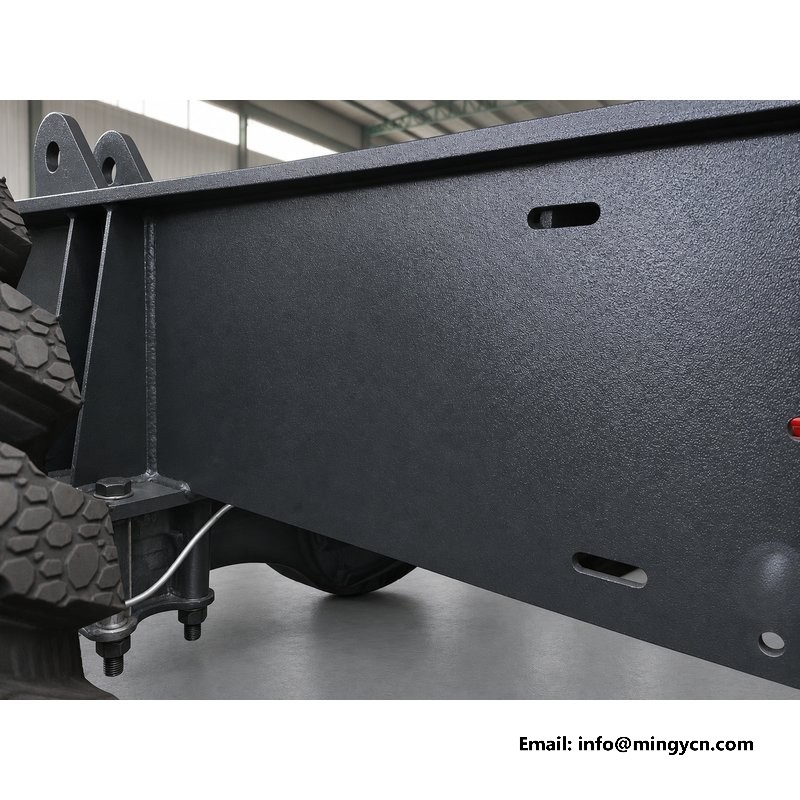
The structural side is equally calm: the reaction torque travels from the gearbox through the machined mounting plate into the drum saddle and the chassis below it, visible in the photograph, which is why the saddle welds never see a shock they were not drawn for.
| Drum drive reference — 0.8 m³ self-loading concrete mixer | |
|---|---|
| Drum drive type | hydraulic orbit motor, 2-stage planetary reduction |
| Rotation | reversible, proportional to lever travel |
| Supply | engine-mounted gear pump, shared circuit with priority valve |
| Filtration | suction strainer plus full-flow return filter |
| Oil tank | finned steel tank with level gauge and drain |
| Lines | steel pipe runs, flexible hose at moving joints |
| Rated drum capacity | 0.8 m³ per batch |
Motor displacement and gearbox ratio are matched at the factory to the drum; both appear on the full specification sheet issued with quotations.
The drive’s maintenance fits on an index card. Daily: glance at the tank gauge and wipe the cooler fins. Weekly: check the return filter indicator, grease the coupling nipple, look at the motor shaft seal. Annually: change the hydraulic oil and filter, check the gearbox oil level, inspect the splined coupling. That is the whole programme. A drive maintained this way routinely outlasts the engine beside it.
The one habit to forbid is washing the motor at close range with a pressure lance while the shaft is turning; water past the shaft seal is the fastest way to ruin an otherwise unkillable component.
Three symptoms cover nearly every field call on this drive. Drum slow when hot, normal when cold: oil is thin or the cooler is blocked, so clean the fins and check the grade. Drum not turning at all with the lever applied: the coupling spline has sheared or the motor has failed; inspect the coupling first because it is the fuse. Knock on each reversal: spline slack, grease or replace the coupling. Everything else on this circuit fails slowly enough to plan the repair around the pour.
One return filter element, one suction strainer, a gearbox seal kit, a motor shaft seal and a splined coupling weigh almost nothing together and cover the realistic failure list for years. They ship inside the drum, cost less than a single day of site downtime, and every one of them is a standard part available regionally once the initial set is used.
A hydraulic drive forgives a cold start better than any mechanical alternative, provided the operator gives it one minute. Oil warmed by slow circulation reaches the motor bearings and the gearbox splash before any load arrives. The correct first action is drum rotation at low throttle, empty, both directions, while the walk-around is done. By the time the first shovel of aggregate enters the mouth, the whole circuit is at working temperature and the day begins without a single cold-side stress on any seal in the system.
Crews that inherit this habit from a belt-driven machine sometimes skip it because belts have no feelings. The hydraulic system has exactly one: it wants its oil warm before heavy work. One minute is the entire price.
Because the drive is photographed bare here, it also makes a fair comparison point between quotations. Three questions separate a serious drive from a dressed-up one. Is the reduction a two-stage planetary in a cast housing, or a single stage in a weldment? Is the motor an industry pattern whose parts list is published, or an unbranded unit with no regional stock? And are the fixed lines steel with individual clamps, or hose run in bundles? The answers predict the second year of ownership more reliably than any price difference in the quotation.
Suppliers confident in their drives answer all three with photographs and part numbers. The photographs on this page exist so that buyers can hold this drive to exactly that standard.
It is worth saying plainly what these photographs are for. A drum drive cannot be judged from a finished machine standing in a yard, and quotations never carry enough detail to compare. Bare-component photography closes that gap. A buyer can see the motor pattern, count the planetary stages from the housing shape, check that the coupling is splined rather than keyed, and confirm the lines are steel. Every one of those details is a promise about the second and third year of ownership, and every one of them is visible here before the order is placed.
Chains on a mixer live in cement dust and need tensioning exactly when the crew is busiest. They also cannot reverse as smoothly, and drum reversal is how discharge happens. The hydraulic route costs a little more and removes the entire category of chain problems.
Yes, at the emergency socket on the gearbox input, slowly, for discharge in an emergency. The manual shows the procedure. It is a get-the-batch-out feature, not a working mode.
Above the point where the tank paint is uncomfortable to touch, check the cooler. The gauge that matters is behaviour: drum speed that holds from the first batch to the last means the temperature is inside the window, whatever the weather.
The orbit motor is a standard industry pattern with the displacement the mixer design calls for. Regional hydraulic shops stock the pattern or its equivalent, and the factory parts list names it openly.
Contact MINGYI Machinery for the current 0.8 m³ self loading concrete mixer specification, the hydraulic drive parts list and a formal quotation for your market. E-mail: sales@mingycn.com | LINE (ID): mingyicn
For the drum this drive turns, read the mixing drum page in the mini self loading concrete mixer category, and for the machine as a whole, Reinforced Axle 0.8m3 Self Loading Mixer for Unpaved Sites. Practical buying notes are in the self loading mixer guides.