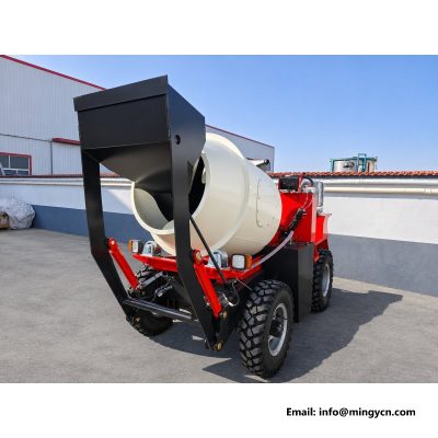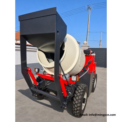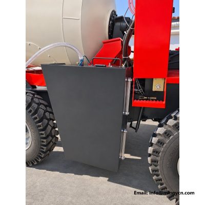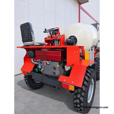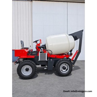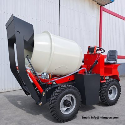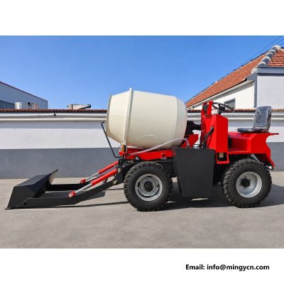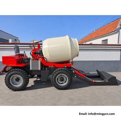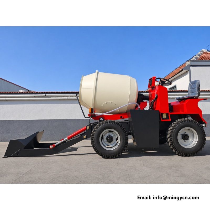
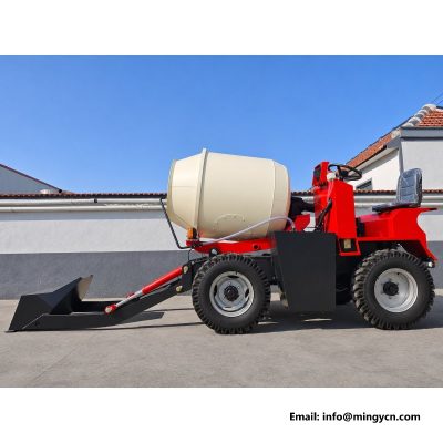
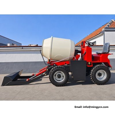
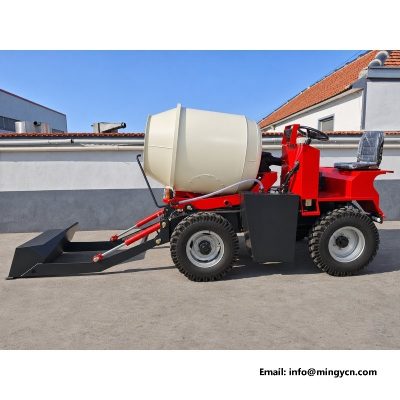
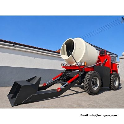
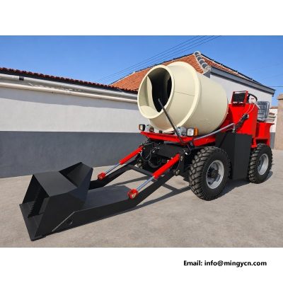
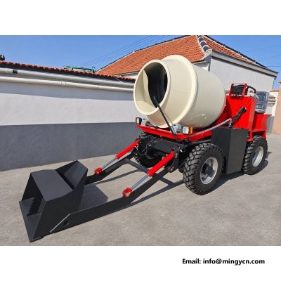
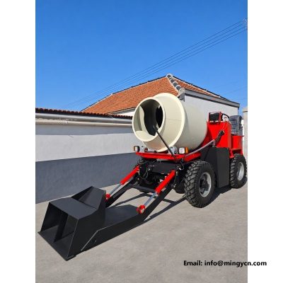
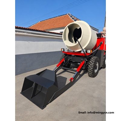
bucket to drum mouth: transfer alignment
The transfer is the shortest and most demanding part of the cycle. The bucket has to arrive above the drum mouth, at the right height and the right angle, and the load has to leave it in a stream rather than a lump. These eight frames keep the bucket and the mouth in one view so the overlap can be judged as geometry rather than guesswork. What they show is a narrow margin: a little too low and the lip catches the rim, a little too high and the material spreads. Everything else on this page follows from that narrow margin.
| Specification | 1.5 m³ self loading mixer |
|---|---|
| Rated load | 5,000 kg |
| Drum capacity | 1.5 m³ (1,500 L) |
| Overall dimensions (L x W x H) | 3,500 x 1,600 x 2,200 mm |
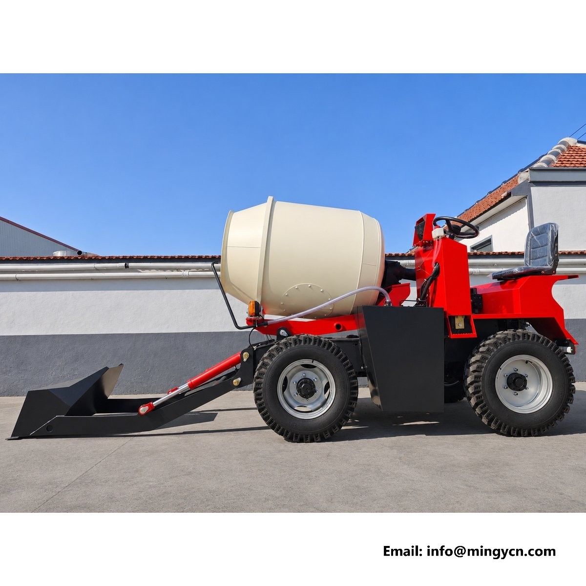
A transfer from bucket to drum mouth is a geometry problem that lasts a few seconds. The bucket has to arrive above the mouth, at an angle where the material will slide, with enough height for the lip to clear the rim and enough overlap that the falling stream lands inside. Everything about the manoeuvre follows from those conditions. In the frames on this page the bucket and the mouth are in the same view, which is the only way to judge the overlap honestly. Read the two edges against each other: the lip and the near rim. The horizontal distance between them is the margin the operator has, and it is smaller than most people expect. The margin is set by the width of the bucket against the width of the mouth, and it does not improve with experience.
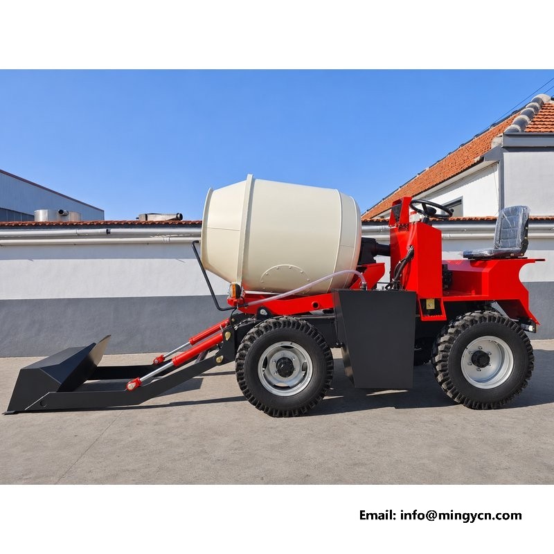
From the seat the mouth is partly hidden by the bucket, so alignment is done by reference rather than by direct sight. The operator lines up a point on the bucket, usually a corner or a wear strip, with a point on the drum, and holds that relationship while the arm rises. Photographs taken square to the machine show how narrow the useful window is: the bucket is barely wider than the mouth, so a small error in yaw puts one corner over the rim and the other over air. In the frames here the bucket sits centred, with equal margins visible on both sides, which is what a correct line looks like before the tip begins. A mark painted on the bucket edge, aligned with the drum centre, removes most of the guesswork from the approach.
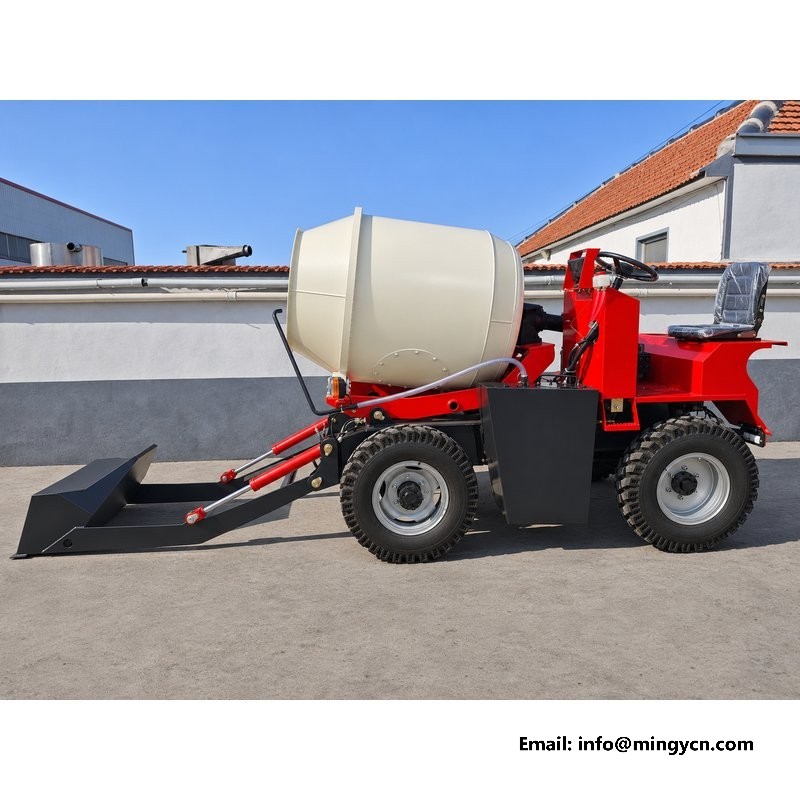
The lip must clear the rim before the bucket tips, and it must not clear it by so much that the material falls from a height. That is the whole tension of the manoeuvre. Too low and the lip catches the rim, dragging the bucket and spilling at the near edge. Too high and the stream spreads, dust rises, and the mix lands off centre. The photographs here catch the bucket at a height where the lip sits just above the rim, which is the position a practised operator reaches and holds. Judging it from the ground is easier than judging it from the seat, which is why a second person watching helps even on a one-man machine. Watch where the material lands in the drum, not where it leaves the bucket, because the two are not the same point.
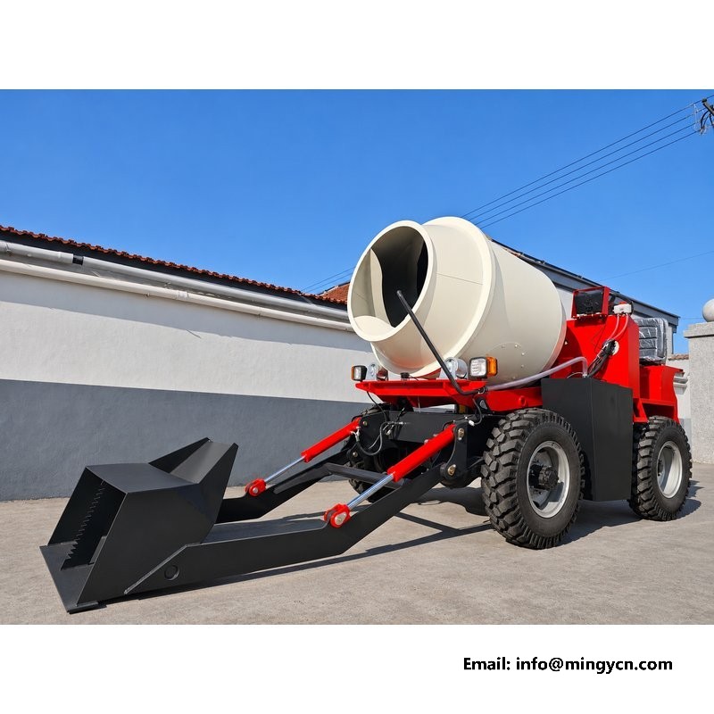
The tip is not a dump. It is a controlled pour, and the lever is the throttle for it. A bucket rolled quickly throws its load in one mass, which arrives at the mouth faster than the drum can take and spills over the rim. A bucket rolled slowly lets the material slide in a stream the operator can stop at any point. In the frames here the bucket is at a shallow angle, which is the position for the start of a pour rather than the end of one. The hydraulic circuit is what makes that possible: with the engine at working speed, the lever has enough travel to give fine control near the beginning of its stroke. The last part of the pour is the part that spills, so the lever should be almost closed before the bucket reaches the empty position.
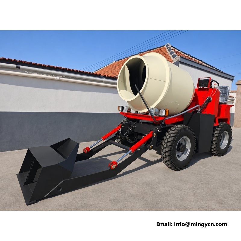
Material that misses the mouth does not disappear. It lands on the drum shell, on the frame behind the arm, or on the ground beside the machine, and each of those has a consequence. On the shell it sets and adds weight high up. On the frame it packs into the space around the pivot and holds moisture against the steel. On the ground it becomes a slip hazard and, over a season, a ridge that changes how the machine stands. The photographs here show a clean shell and a clear frame, which is what a disciplined operator leaves behind. Ask for a picture of the machine after a shift, not after a wash. A sheet of ply on the ground beside the machine catches most of it, and a sheet is easier to clear than a frame full of set mix.
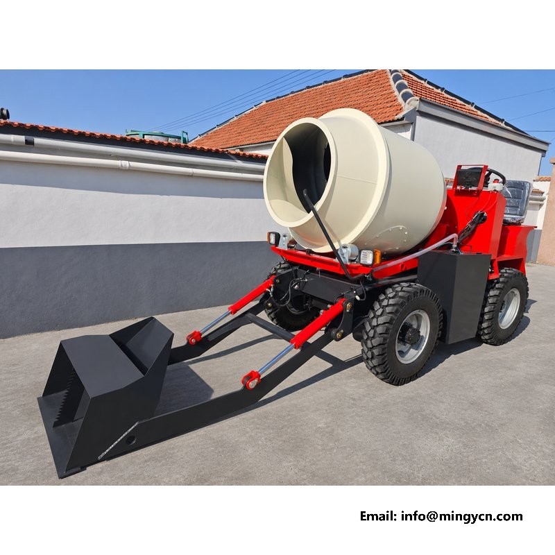
An experienced operator does not watch the bucket during the pour; they feel it. The lever loads up as the bucket takes the weight of the material, lightens as the load slides, and kicks slightly when the bucket passes the angle where the mix runs freely. That feedback comes through the hydraulic circuit, and it is the reason a machine with a well matched pump and valve is easier to load than one with a bigger pump and a crude valve. In these frames the lever is held at a small angle, which is consistent with a slow pour. None of that can be photographed directly, but the bucket attitude in the picture is its result. The same feel tells you when the drum is approaching full, because the last of the load slides more slowly than the first.
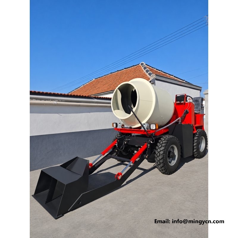
Dry sand and fine aggregate behave differently from wet mix, and a crosswind turns a controlled pour into a spray. The material leaves the lip with almost no cohesion, so any lateral air movement carries the fines away from the mouth. The response is not to tip faster but to get closer, keep the drop short and work with the wind rather than across it. In the frames here the bucket is close to the mouth and the pour angle is shallow, which reduces the distance the material falls and the time the wind has to act on it. On an open site the loading position should be chosen with the wind in mind, not just with the stockpile. On a still day the dust hangs over the mouth, a useful reminder that the fines leave the bucket before the coarse material does.
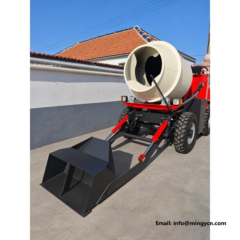
Several errors appear together often enough to be recognisable. The bucket is tipped before it is over the mouth, so the first of the load goes onto the shell. The lip is below the rim, so the bucket rests on the drum instead of clearing it. The machine stands at an angle to the mouth, so one corner overhangs. And the bucket is overloaded, so material is already sliding off the back before the tip begins. In a single frame these read as a bucket that is too low, too full and slightly crooked. Any one is correctable in the moment; all of them together mean the operator is working at the limit of the machine rather than within it. Read the frame for the bucket angle first, because the other errors usually follow from a bucket tipped too early.
A rim with dried mix on it changes the transfer. The material builds up on the near edge, the effective opening narrows, and the bucket has to be brought higher to clear a lip that is now thicker than it was. It also hides cracks at the rim, which is where a drum mouth usually starts to fail. Cleaning takes a scraper and a couple of minutes between batches, and it belongs in the cycle rather than at the end of the day. In the frames here the rim is clean and the mouth fully open, which is how the machine should look at the start of a pour. Build-up on the rim is visible from the seat and should be dealt with before the next bucket. A rim scraper kept on the machine is worth more than a chisel kept in the workshop.
A photograph of a good transfer proves that the geometry works; it does not prove that the operator can repeat it. Judging a machine from this angle tells you whether the mouth is reachable, whether the bucket clears the rim, and whether the sight lines allow the operator to see what they are doing. It does not tell you how the hydraulics feel at the moment the load slides, or how the machine behaves when the drum is half full and the ground is soft. Those are questions for a demonstration. Use the picture to decide whether the machine is worth demonstrating, and the demonstration to decide whether to buy it. Ask for a demonstration with the drum at working weight rather than empty, because the geometry changes when the machine is loaded.
Just enough for the lip to clear the rim, and no more. A short drop keeps the stream together and limits what the wind can do to it; a high drop spreads the material and sends fines into the air. The bucket should also overlap the mouth rather than stop short of it, so the load falls inside the rim even when the pour is not perfectly controlled.
Usually because the bucket is tipped before it is fully over the mouth, or because the lip is below the rim, so the bucket rests on the drum and the load slides off the near edge. Overloading has the same result, with material already running off the back before the tip starts. All three are visible in one frame as a bucket that is low, full and slightly crooked.
For the current specification, build options and a formal quotation for your market, contact MINGYI Machinery. E-mail: sales@mingycn.com | LINE (ID): mingyicn
Drum Mouth, Discharge and Pour Control on the 1.5m3 Self Loading Mixer · Loading Hopper and Lift Arm on the 1.5m3 Self Loading Mixer · 1.5m3 Self Loading Mixer from Every Angle: A Yard Photo Reference