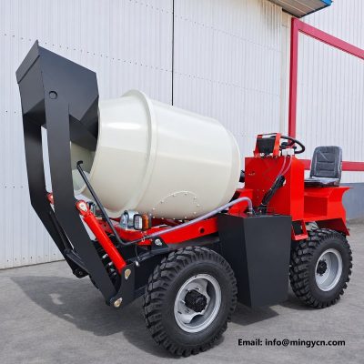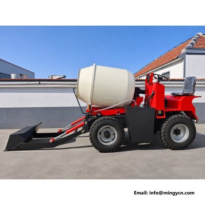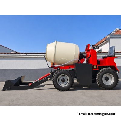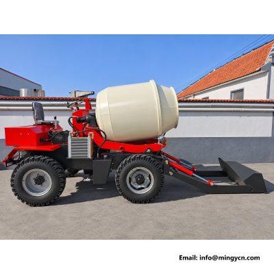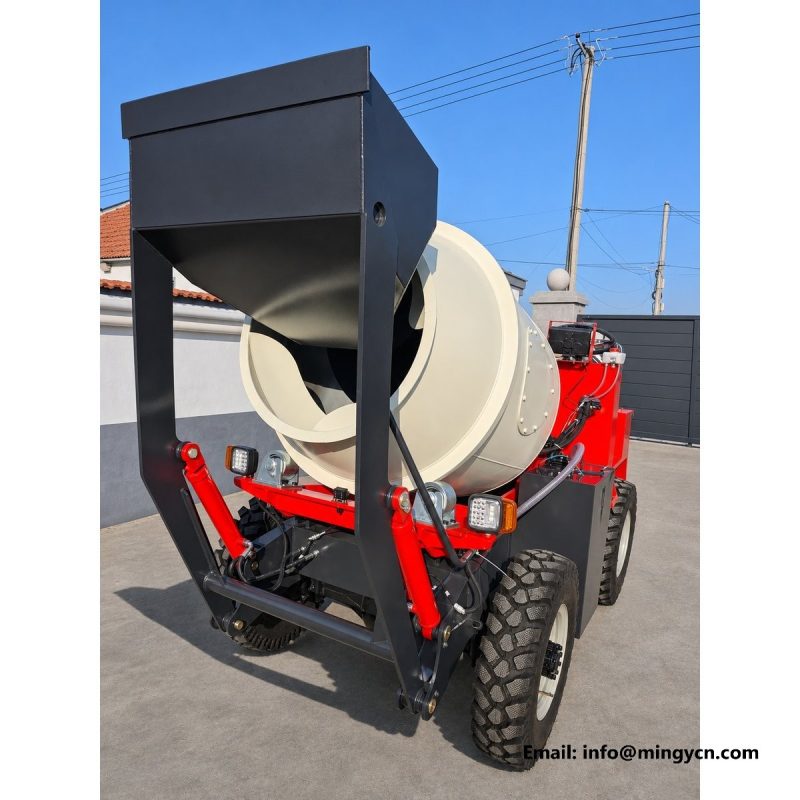
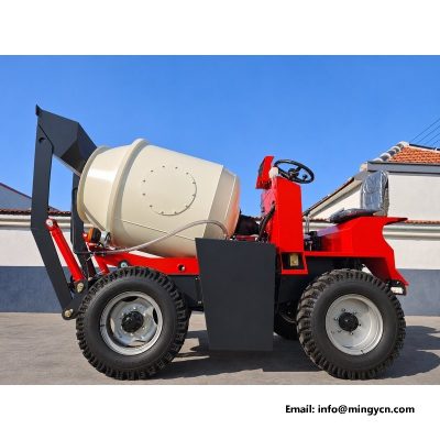
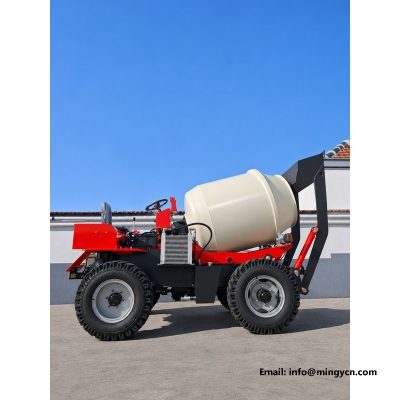
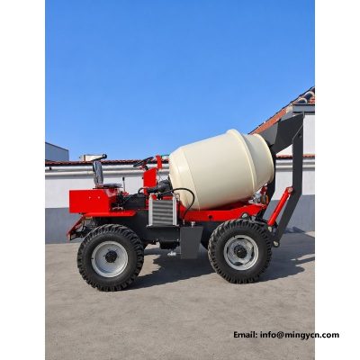
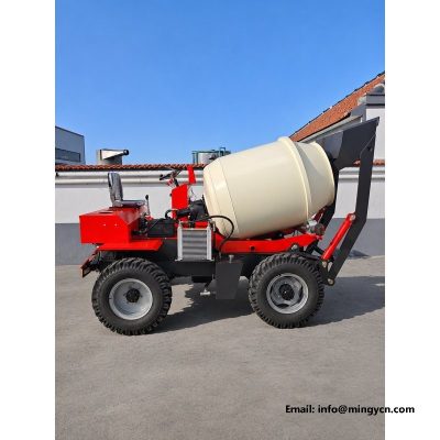
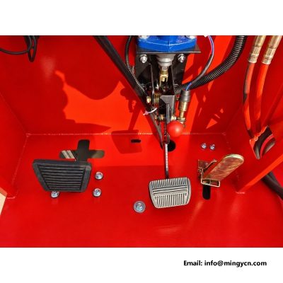
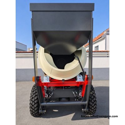
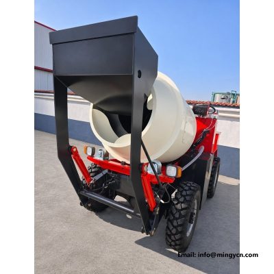
hydraulic fittings and bucket detail
Hydraulic faults rarely begin at the cylinder. They begin at a fitting, a crimp or a coupler that was left open to dust, and they announce themselves as a film of oil long before anything stops working. This set concentrates on those small parts, then pulls back to the bucket that depends on them. Four frames deal with connections and their condition; the rest deal with the hopper shell, its ribs and its edge. Together they support a short inspection routine that a buyer or a site fitter can repeat in a few minutes, and a list of spares worth holding before the machine starts earning its keep on site.
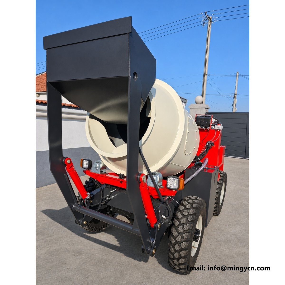
| Specification | 1.5 m³ self loading mixer |
|---|---|
| Rated load | 5,000 kg |
| Drum capacity | 1.5 m³ (1,500 L) |
| Transmission | 4WD, 3 forward + 1 reverse + road gear |
A hydraulic cylinder is a reliable component that usually fails for a reason outside itself. The reason is nearly always at a connection: a coupler left open, a hose crimped too tight, a fitting screwed in with tape wrapped the wrong way, or a cap dropped in the dirt and pushed back on. That is why this set begins at the fittings rather than at the ram. The close frames show the couplers, the hose ends and the ports they enter, at a scale where the condition of a seal or the angle of a hose is visible. A buyer who learns to read these few square centimetres can judge the standard of assembly on the whole machine, because the same pair of hands usually built all of it.
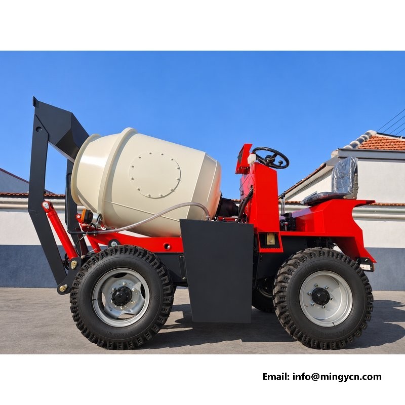
Quick couplers exist so that a hose can be separated without tools, and they are also the easiest place on the machine for dirt to enter the circuit. A coupler left uncapped on a site collects dust in the female half, and the first time it is connected that dust is pushed into the oil. Look at the photograph for caps that are tethered to the coupler rather than lying loose, and for coupler bodies mounted so the open end faces down when disconnected. A flat-face coupler is more forgiving than a poppet type because it has no cavity to trap dirt, but neither survives being dragged through mud. Ask how the couplers are protected in transit, then look for the answer in the frame.
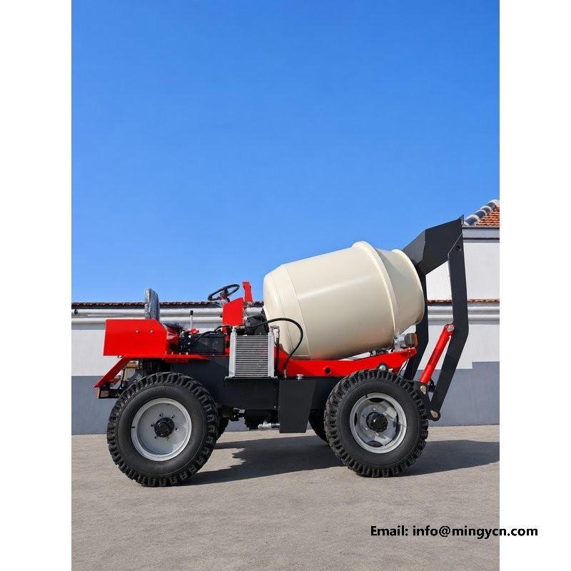
Threads on hydraulic fittings are not interchangeable, and the most common field error is to treat them as if they were. Some connections seal on the thread, some on a face, and some on an O-ring in a groove. A fitting that seals on a face will not be made tight by more tape; it will be made tight by a clean, undamaged face and the correct torque. Look at the photograph for shreds of thread tape hanging from a joint. Tape that enters a circuit will block a valve or a filter, and it is a sign that whoever assembled the joint did not know which seal was doing the work. Look also for fittings sitting at an odd angle, which usually means a hose was pulled into place rather than routed to it.
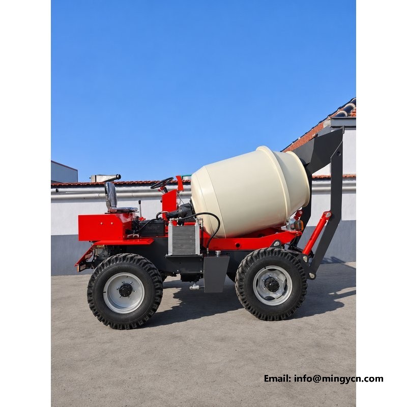
A photograph can distinguish three states at a fitting, and the distinction is worth learning. A film is a thin dark sheen with dust settled into it, often left by assembly oil or a single hot cycle, and it is not a leak. A weep has a defined track with a clean edge, which means oil has run and stopped, usually after the machine cooled. A drip is wet, has a fresh line and leaves a mark below. In this set the fittings are dry and the only sheen is at a joint that has just been assembled, which is how a machine should look before dispatch. On a used machine, clean the area first and photograph it again after an hour of work; a weep that returns is still active.
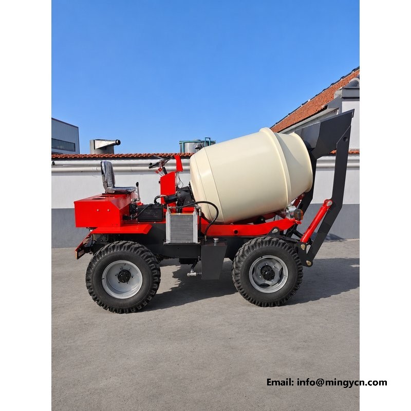
A hose fails at its weakest point, and that point is almost always where the metal ends. The crimp should be even around the collar, with no step or sharp lip where the rubber meets it, and the hose should leave the fitting straight for a short distance before it begins to bend. A bend that starts immediately at the collar works the reinforcement every time the circuit pressures up. Then follow the hose with your eye along its run and look for the place it touches something. Abrasion shows as a dull patch or a flattened cover, and it usually appears at a clamp, a frame edge or a cross-over with another hose. A sleeve at that point costs very little and prevents the failure that strands the machine.
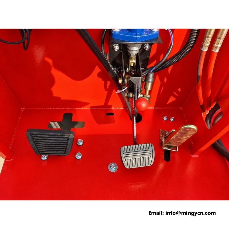
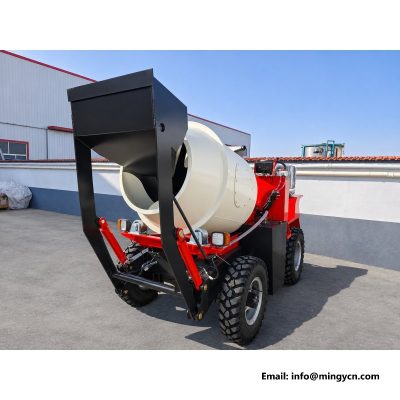
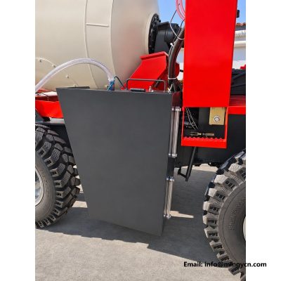
The hopper is a box that has to survive being filled by a machine and emptied by gravity, and its walls are loaded differently from a simple trailer body. The side plates take the outward push of the load; the floor takes the scrape of the bucket edge; the front edge takes the impact when material is dropped in. Ribs and gussets are placed to carry those loads into the frame, so their position matters more than their number. In the frames here, the ribs land at the panel centres and run down to the floor seam rather than stopping short, which is the arrangement that keeps a wall from bowing outward. Look for a rib that ends in mid-air, and for cracks at the toe of any weld joining a rib to a plate.
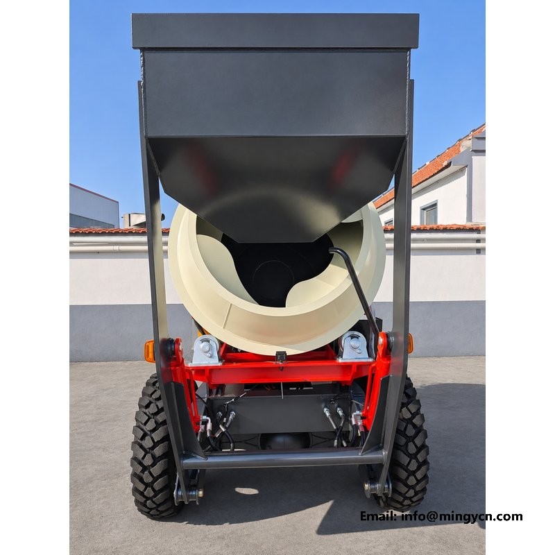
A loading bucket wears along a line, not across a face. The edge that scrapes the stockpile loses material first, and the plate behind it thins gradually as abrasive material is dragged over it. In the photographs, look at the straightness of the cutting edge and at the height of the wear plate behind it. An edge that has been built up with weld in the field is acceptable if it is dressed smooth, but a row of hard beads left proud will catch on the stockpile and load the arm unevenly. Then look at the hinge points where the bucket meets the arm. The pin should be retained positively, with a visible cap or collar, and the boss should be greased, since this joint moves under the full weight of every scooped load.
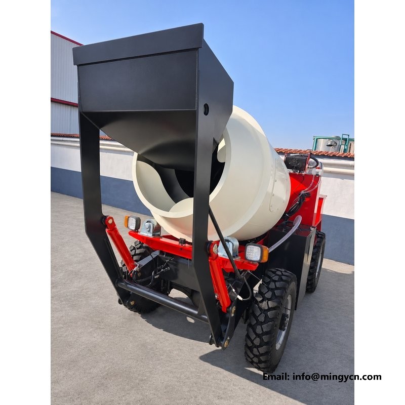
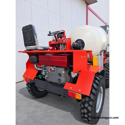
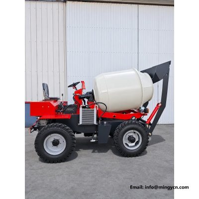
A walk-around is only useful if it is done the same way every time, because the value comes from noticing what has changed rather than from the inspection itself. Start at the front left tyre and work clockwise: tyre and rim, bucket edge, arm pins, hose bundle, fittings at the valve block, water tank connections, drum mouth, then the rear axle and the lights. At each fitting, look for wetness rather than for a leak, and touch the coupler caps to confirm they are seated. The whole circuit takes a couple of minutes and needs no tools. What it produces is a baseline. Once an operator knows what the machine looks like when it is right, the first trace of oil stands out immediately.
Bolted joints on a hydraulic machine settle in the first hours of work, as paint and plating compress and gaskets take a set. That is why the fittings and the mounting bolts should be checked early rather than at some distant service interval. The check is simple: a wrench on each fastener in sequence, to the specified torque, followed by a paint stripe across the head and the adjacent metal. The stripe is not decoration. It lets anyone see at a glance whether a bolt has moved since it was checked, and it shows a buyer that the machine was commissioned properly. Record the date and the hours on the machine when the check was done, and keep the record with the manual rather than in someone's memory.
The parts that stop a machine are rarely expensive, and they are almost always small. A set of coupler caps, a handful of O-rings in the sizes used at the valve block, one spare hose for the most exposed run, and a seal kit for the lift ram will cover most of what a site can repair without help. Before ordering, ask which of these are standard parts and which are specific to the machine. Standard parts can be bought locally on a Saturday; specific ones have to come from the supplier, and that difference decides how long the machine stands. Photograph the fittings on the machine and keep the images with the parts list, so whoever buys the spares can match the thread without guessing.
That depends on the thread and the coupler series, and both should be confirmed in writing before you order spares. Ask the supplier for the coupler type and the thread form, then compare it with what is available locally. A standard coupler can be replaced in a day; a proprietary one has to come from the factory. Photograph the coupler body and the cap together, since the cap often carries the series marking.
The valve block, taken square on, with the fittings in focus and the area dry and clean. It shows the standard of assembly better than any other frame: whether the hoses enter squarely, whether the clamps are evenly spaced, and whether there are signs of weeping at the ports. Ask for a second frame of the same area after an hour of work. The difference between the two is more informative than either alone.
For the current specification, build options and a formal quotation for your market, contact MINGYI Machinery. E-mail: sales@mingycn.com | LINE (ID): mingyicn
Hydraulic Valve Block and Drum Drive on the 1.5m3 Self Loading Mixer · Loading Hopper and Lift Arm on the 1.5m3 Self Loading Mixer · 1.5m3 Self Loading Mixer from Every Angle: A Yard Photo Reference