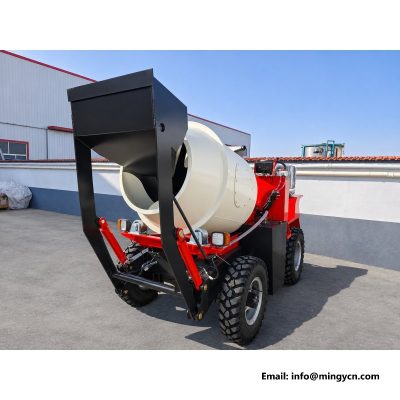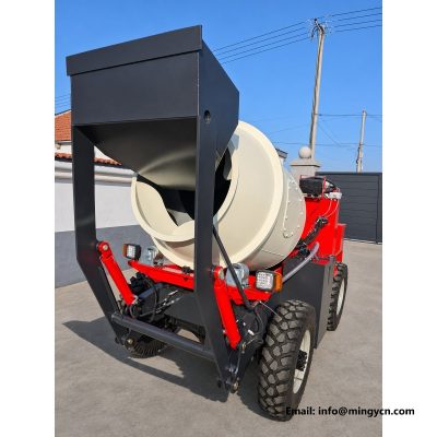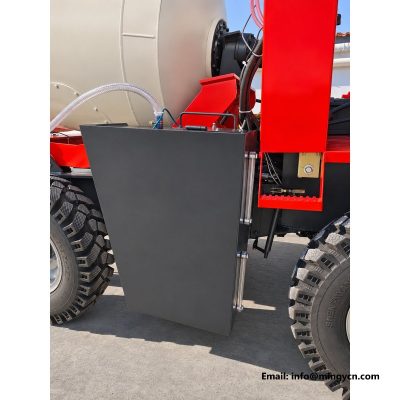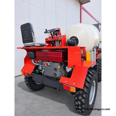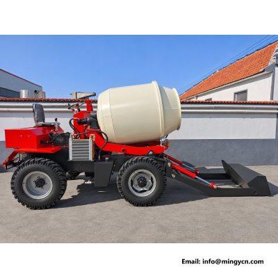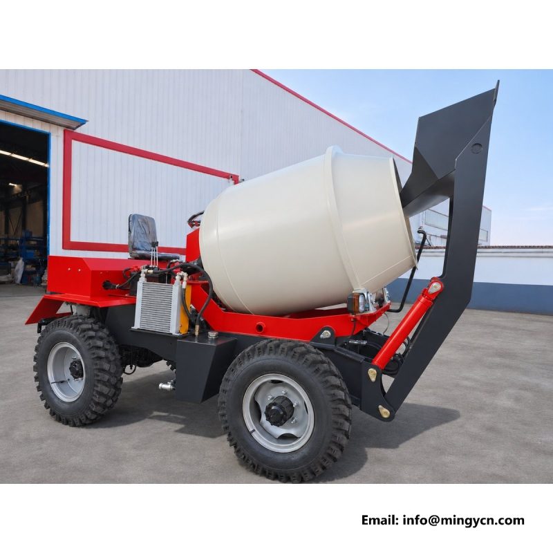
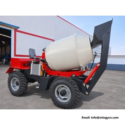
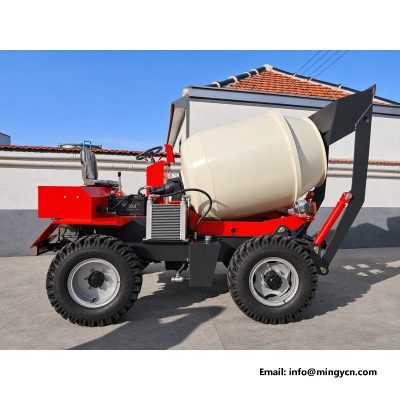
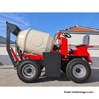
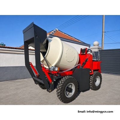
1.5m3 self loading mixer photo reference from every angle
Most product pages describe a machine and then show one photograph of it from the front. This one does the opposite. It takes eight frames of the same 1.5 m3 self loading mixer, shot from eight positions in the factory yard, and explains what a buyer can verify in each of them. The machine is the standard build with the cream drum and red frame, the light is natural and the ground is concrete. Nothing in the text is a sales claim. Each section names an angle, describes what is visible in that frame, and suggests the question to put to a supplier before an order is placed.
| Specification | 1.5 m³ self loading mixer |
|---|---|
| Rated load | 5,000 kg |
| Drum capacity | 1.5 m³ (1,500 L) |
| Operating weight | 1,900 kg |
| Overall dimensions (L x W x H) | 3,500 x 1,600 x 2,200 mm |
| Front tyres | 750-16 |
| Rear tyres | 750-16 |
| Minimum ground clearance | 204 mm |
| Steering angle | 28 degrees |
| Turning circle (outer tyre) | 2,464 mm |
| Transmission | 4WD, 3 forward + 1 reverse + road gear |
| Maximum travel speed | 24 km/h |
| Front axle | Isuzu-type reinforced |
| Rear axle | 130 four-wheel steering |
| Engine | Single-cylinder diesel, 25 hp |
| Steering | Hydraulic power steering |
Specifications describe a machine; photographs show whether the machine in front of you matches them. This page is built around eight frames of the same 1.5 m3 self loading mixer, taken in the factory yard on the same afternoon, from positions a buyer would otherwise have to travel to see. Nothing here replaces the dimensions: 3,500 x 1,600 x 2,200 mm overall, 1,900 kg operating weight, 204 mm minimum ground clearance, 750-16 tyres front and rear. Those numbers belong on the specification page. What the photographs add is the evidence behind them: how the drum sits on the frame, how the pipes are run, whether the paint is even, and whether the machine looks like a prototype or a product. Read the frames in order and treat each one as a question.
A photograph is good evidence and bad proof, and knowing the difference keeps a buyer from over-reading a single image. It can show the shape of a weld, the presence of a gusset, the route of a hose and the gap between drum and frame. It cannot show steel thickness, weld penetration, bearing grade or the torque on a bolt, and no image will tell you how the machine behaves after a season of gravel. Use the frames to build a list of questions, then ask the supplier for the answers in writing. Where a photograph raises a doubt, request a close-up of the same area with a rule or a gauge in frame. A supplier who produces that second image within a day has the machine on the floor rather than on a brochure.
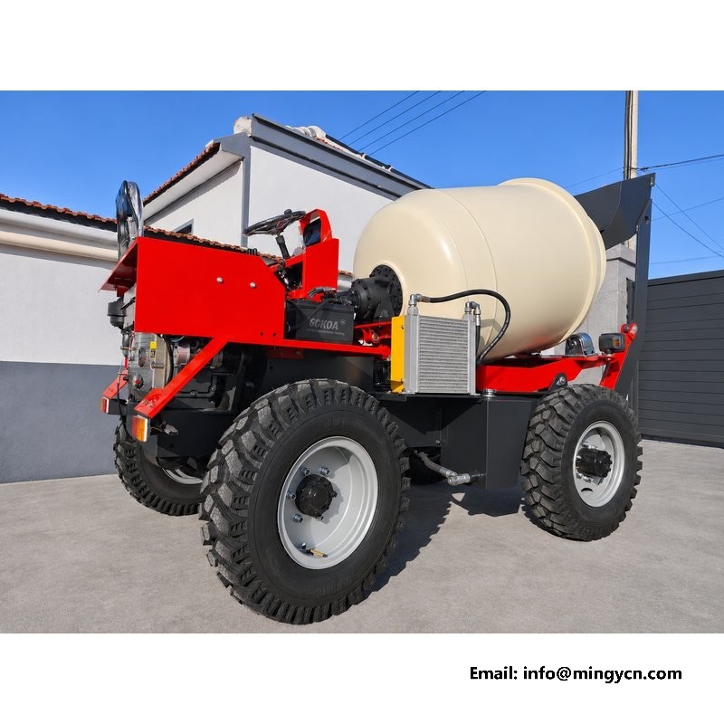
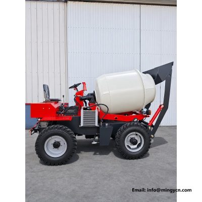
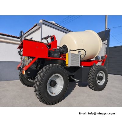
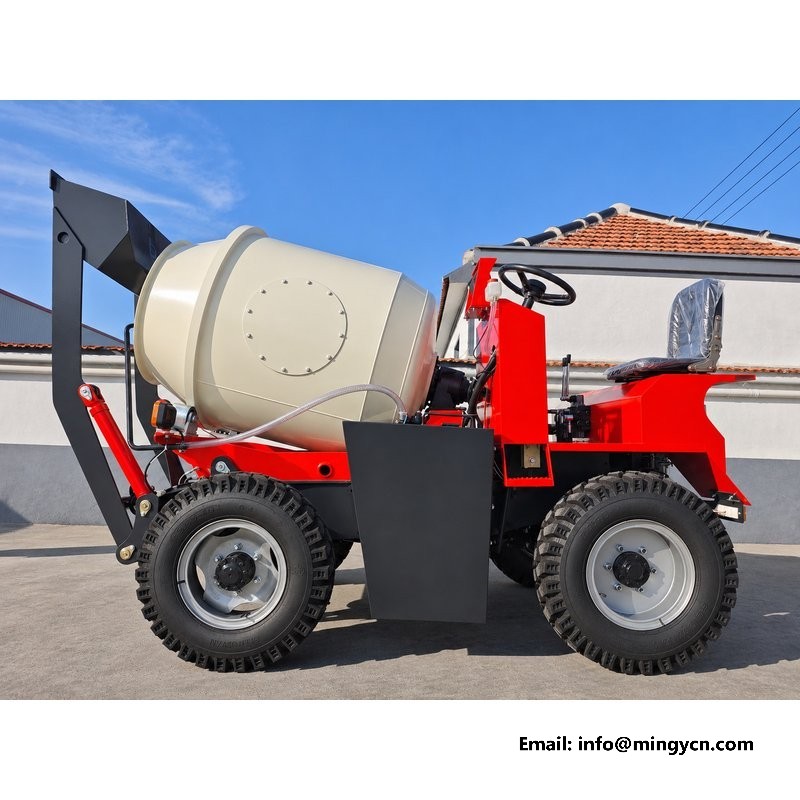
The left front three-quarter is the angle that shows the machine as a whole: the front axle, the frame rails behind it, the drum saddle and the relationship between the wheels and the body. On this machine the front axle is an Isuzu-type reinforced unit, and the frame ahead of it carries the hopper arms and the steering gear. Look at the tyre in this frame. The 750-16 fitment should sit square under the mudguard with even clearance on both sides, and there should be no sign of the rim being offset to clear a bracket. Look at track width against the drum. A machine narrow at the front and wide at the drum feels unstable on a cross-slope, and the photograph shows that proportion before you ever drive it.
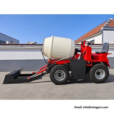
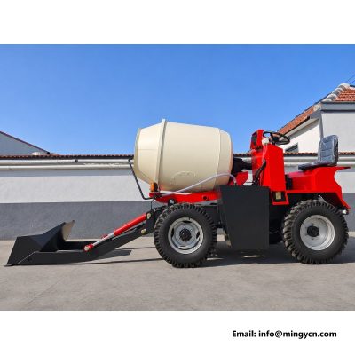
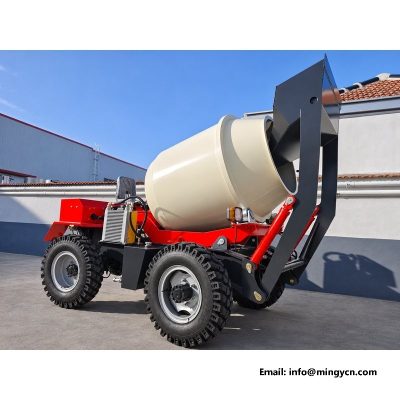
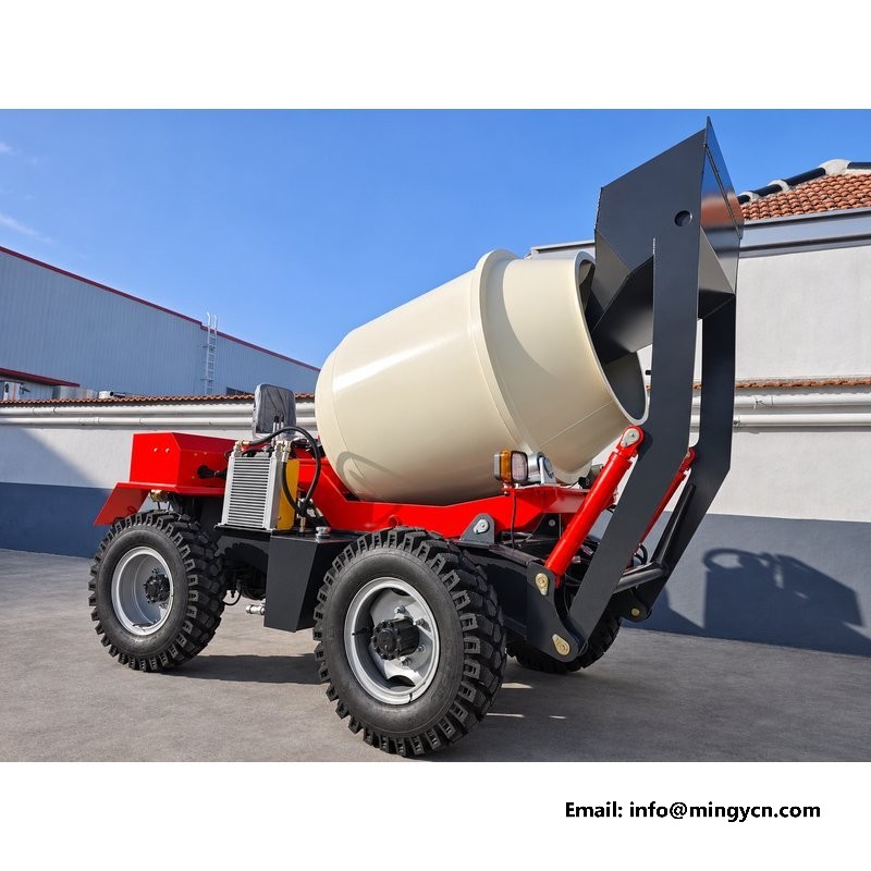
The right front frame puts the hopper and its lift arms in the foreground and pushes the drum back into the picture, which is useful because it shows the two halves of the cycle in one view. What to check here is the alignment of the lift arms: the two should be parallel, their pivot pins fully home, and the ram on each side extended by the same amount when the hopper is down. A machine photographed with one arm slightly ahead of the other has either been parked on uneven ground or has a bent arm, and the two look different once you compare the gap to the frame on each side. Look at the hopper mouth too: a straight edge and an even lip suggest the machine has not been used as a bulldozer.
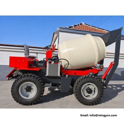
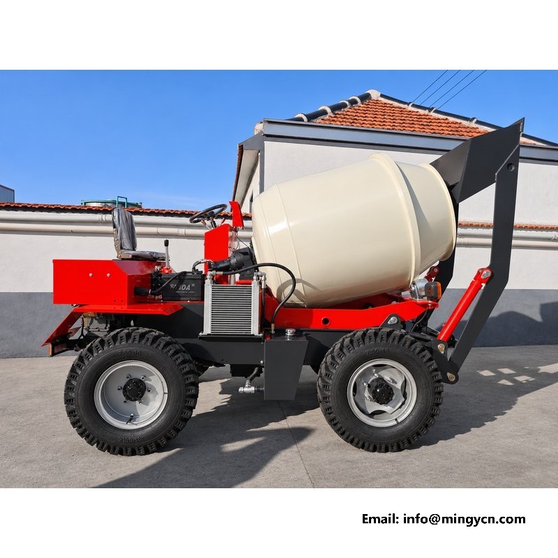
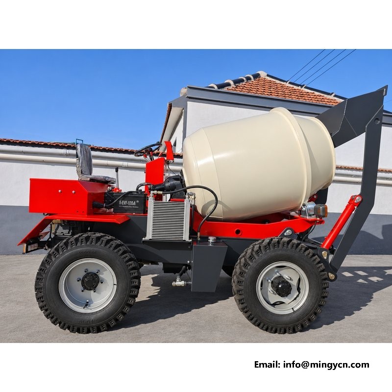
The two side frames are the ones a transport manager reads first, because they show wheelbase and overall length in proportion. Overall length is 3,500 mm and overall height is 2,200 mm, so the machine fits a standard flatbed or a low loader without special permission in most markets, but the side view is where you confirm that the drum does not overhang the rear axle far enough to make loading awkward. Look under the chassis. The 204 mm minimum ground clearance is measured at the lowest point, and the photograph shows where that point actually sits. On this build the sump and the axle housing are the usual candidates, and a machine that drags its bell housing through a rut will lose a drain plug long before it loses traction. That figure is easy to quote and harder to verify, so use the side frame to see what actually hangs lowest.
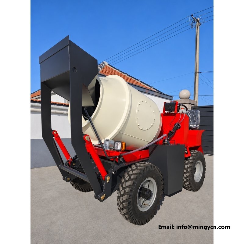
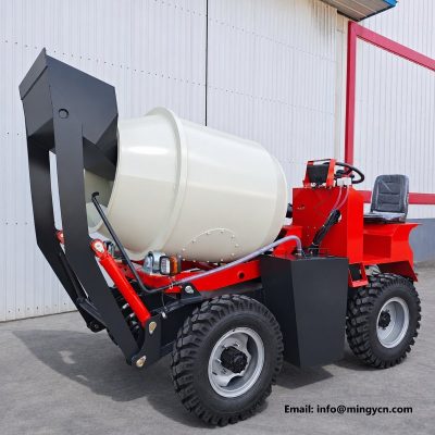
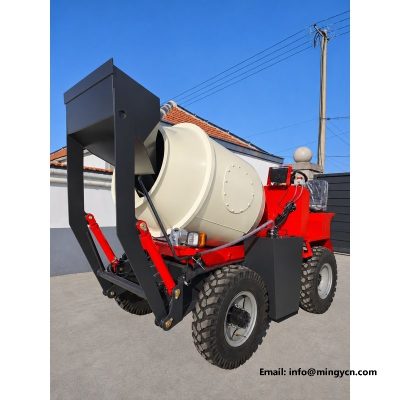
The rear three-quarter frames show the working end of the machine: the discharge side of the drum, the rear axle, the mudguards and whatever the builder has done about access for cleaning. This is the area that takes the most abuse on site, because it is closest to the pour and furthest from the operator's attention. Check the mudguard mounts rather than the mudguards. A guard bolted to a bracket welded to the frame survives a knock; one bolted through a thin panel tears out the first time a wheelbarrow is pushed against it. Look at the space between drum and rear cross member, because that gap is where set concrete collects and where a pressure washer cannot easily reach. Look at the rear lights and reflectors as well, and at the clearance between the mudguard and the tyre under full articulation.
The head-on frame is the least flattering angle for any machine and therefore one of the most useful. Symmetry is easy to judge here: the hopper should sit square between the arms, the two rams should read as a matched pair, and the front axle should be centred under the frame rather than offset to one side. The pivot bosses at the base of the lift arms are the parts to study. They carry the full reaction of a loaded scoop, and in this frame you can see whether they are machined and bushed or simply a pin through a plate. A boss with a visible grease nipple and a bolted cap can be serviced; a plain pin welded into a bracket has to be cut out. That difference outlasts any paint finish.
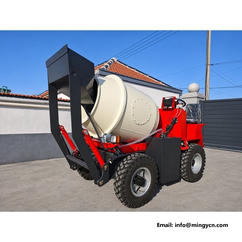
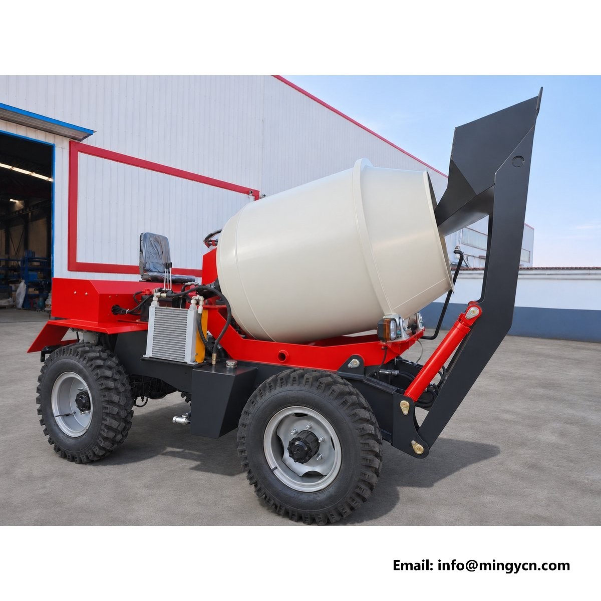
The elevated three-quarter frame answers layout questions a ground-level photograph cannot. From above, the drum sits inside the frame rather than on top of it, the water tank and the engine bay occupy the space behind the operator's platform, and the route of the main hydraulic lines becomes visible as a set of parallel runs rather than a bundle. Look for clearance: the gap between drum shell and the nearest frame member should be even all the way round, because an uneven gap means a mount has settled or a saddle is misaligned. Look also at how the services are separated. A build that runs fuel, hydraulic pressure and electrical cable in the same clip has saved a bracket at the factory and created a fire risk in the field.
Factory daylight is a hard light for paint, and that is why these frames were not shot under a canopy. At this angle a thin coat shows as a grey shadow through the colour, a run shows at the edge of a panel, and a weld painted without being cleaned shows as a rough line under the gloss. None of this is cosmetic on a machine that works outside. Paint is the first barrier against rust, and rust starts at edges, at weld toes and around bolt holes, which are exactly the places a photograph catches. What to look for is consistency: the same finish on frame, drum and the inside of the hopper. A machine glossy outside and bare inside the hopper was painted for the photograph, not for the site.
If you only have one photograph to judge build quality by, make it the one that shows the hoses. Routing is a habit, and a factory that routes well routes everything well. Good routing means hoses that run in straight lines, are supported at regular intervals, cross a weld seam at right angles rather than lying along it, and are held in clamps that are bolted rather than tied. It also means a service loop at every moving joint, so the hose bends over a curve instead of folding at the fitting. Look in the photographs for hoses that disappear behind the frame and reappear without a visible support, or that rub against a plate with no protection. Those machines develop a weep in the first season, and the fault is designed in.
Eight frames are enough to build a working checklist if you use them in a fixed order. Start with the four corners and note tyre condition, wheel nut type and mudguard mounts. Move to the front and check hopper edge, arm alignment and pivot bosses. Take the side views for ground clearance and saddle height, then the high angle for hose and harness routing. Write each observation as a question with a yes or no answer, and send that list to the supplier with the frame number beside each item. A list of twelve specific questions gets a better reply than a request for a catalogue, and it creates a written record you can compare against the machine at inspection, or against the next unit if you order more than one.
Every frame on this page was taken in the factory yard on concrete, in natural light, with the machine parked and the drum empty. Nothing was staged beyond moving the machine between positions, and no frame was shot with a wide lens close to the body, which stretches a machine and makes a narrow build look substantial. The same eight angles are recorded for each unit that leaves the yard, which is why two photographs of the same corner can be placed side by side and compared. Repetition is the point: one frame shows a weld, while two frames taken a season apart show whether that weld is consistent across a production run. When you ask a supplier for photographs, ask for the same discipline, and the images become evidence rather than advertising.
They show a standard production machine in the factory yard, not a prepared display unit. The drum is empty, the machine is clean but not detailed, and the frames include the areas a brochure would normally avoid, such as the underside of the frame and the space behind the drum. That is deliberate. A buyer needs to see the machine as it leaves the line, because a show unit tells you what the factory can do once and a production unit tells you what it does every time.
Ask for them, and ask before the deposit is paid. A supplier who photographs every unit from the same positions can send the set for your serial number, and those images become the reference against which the machine is checked on arrival. Specify the eight positions in writing, request that the drum be empty and the machine on level ground, and ask for the images at full resolution rather than as compressed thumbnails, so weld and paint detail survives.
Ask for a close-up of the same area with a scale in frame, and ask a direct question about it rather than a general one. Instead of requesting more photos of the frame, ask for the plate thickness at the lift arm bracket and a photograph of the bracket with a rule across it. Specific questions produce specific answers, and a supplier who answers them in writing gives you something to compare against the machine when it arrives.
For the current specification, build options and a formal quotation for your market, contact MINGYI Machinery. E-mail: sales@mingycn.com | LINE (ID): mingyicn
1.5 m3 Self Loading Concrete Mixer: Full Specification and Walkaround · 0.8m3 Self Loading Mixer from Every Angle: A Photographic Reference · 750-16 Tyres and Isuzu Front Axle on the 1.5m3 Mixer