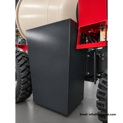
1.5 m3 Self Loading Concrete Mixer Water Tank with Locking Filler Cap, Baffled Steel Tank and Side Mounting Behind the Drum
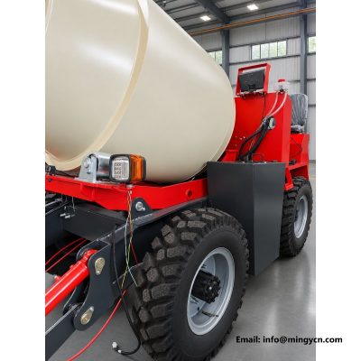
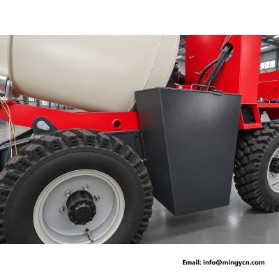
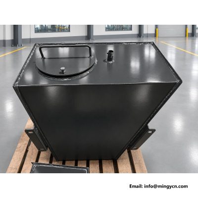
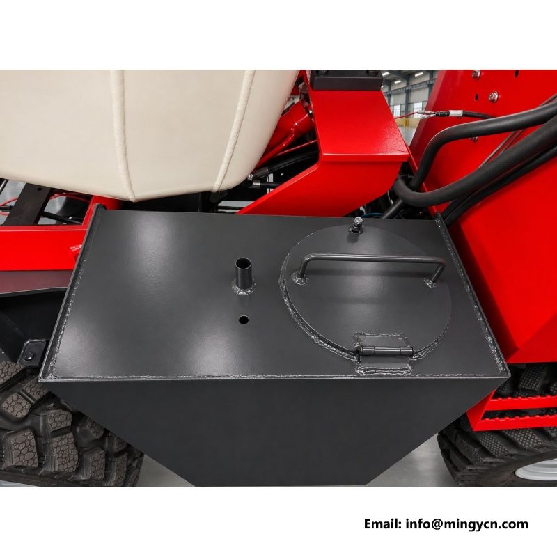
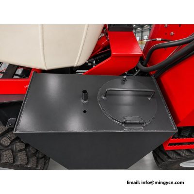
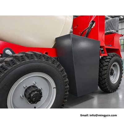
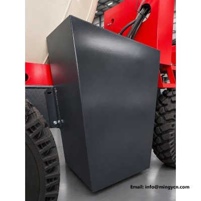
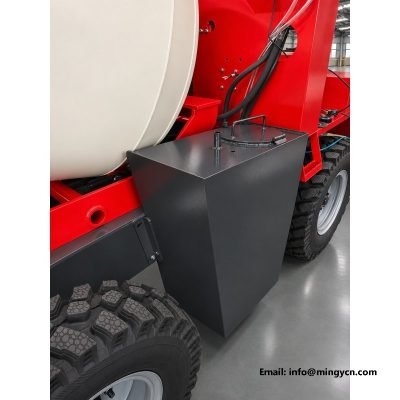
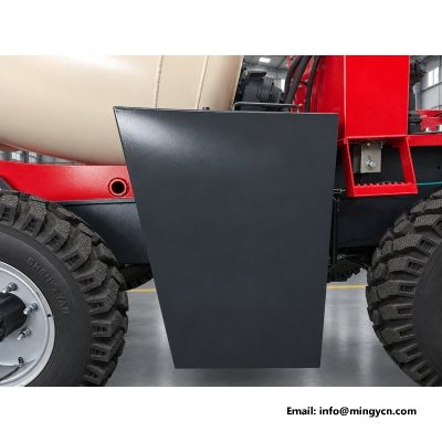
Fitted to the side and rear of the drum, the black trapezoidal steel water tank is easy to overlook in a whole-machine photograph, yet it governs how consistently a self loading mixer doses water into each batch. The close-up set here isolates that tank: the latched filler cap, the flat steel sides, the inspection cover, the fixing points, and how it sits against the rear tyre and drum shell. The notes below explain how the filler seals, how water is measured into the mix, why the tank sits where it does, what that position does to balance, and how to clean, inspect and store it so it never becomes a source of contamination or rust. No tank capacity is assumed beyond the drum rating.
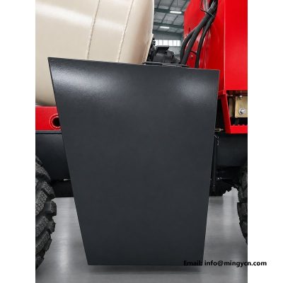
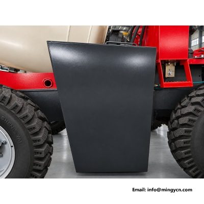
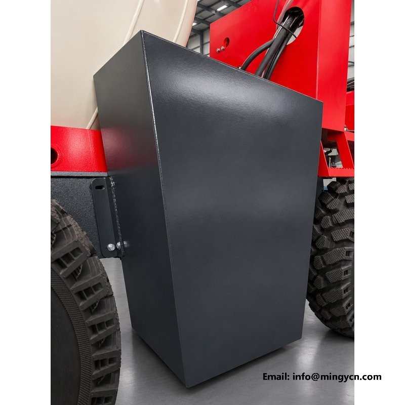
The tank in these close-ups is a trapezoidal steel box rather than a cylinder, and that choice is deliberate. A sloped or tapered side lets the tank tuck into the space beside and behind the drum without stealing clearance from the rear wheel or the discharge chute, so the machine keeps a compact overall width. Flat steel panels are also simpler to cut, fold and weld in a workshop, and easier to strap to a frame than a round vessel. Look at how the panels meet: clean, straight folds and consistent weld beads suggest a jig-built part, while a wavy edge points to hand fitting. For a buyer, the shape is less about appearance than about fit, mounting stiffness and how much freeboard remains at the filler when the machine is parked on a slope.
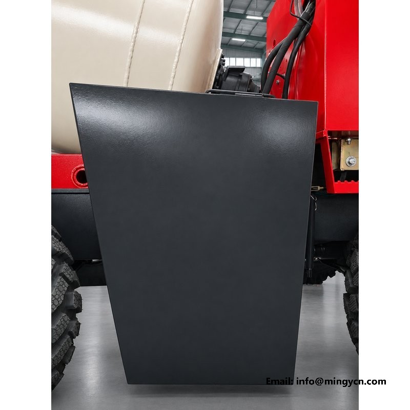
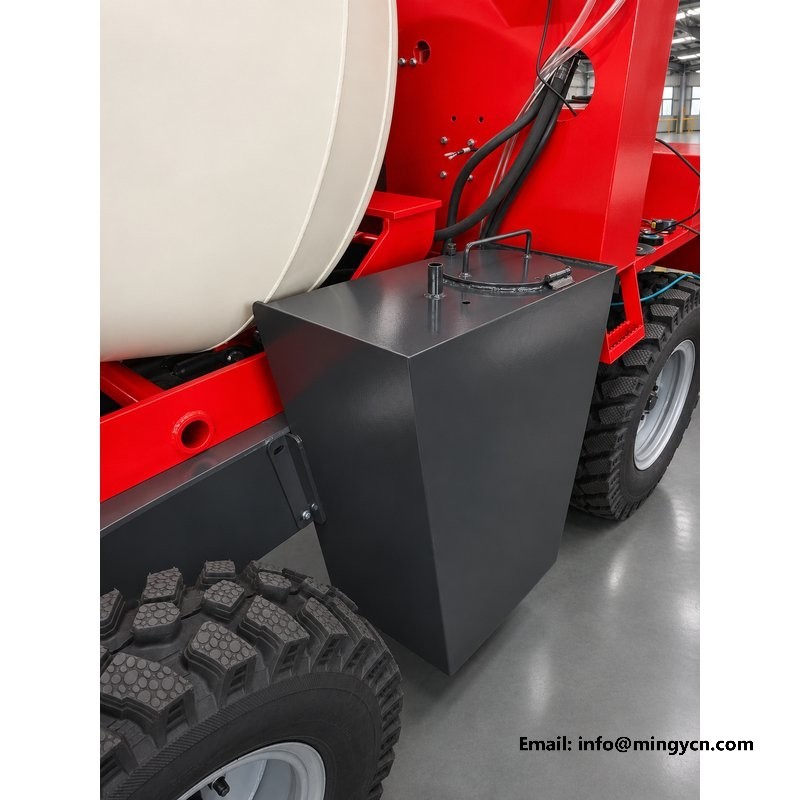
The filler is the part an operator touches every batch, so the cap and its latch deserve a close reading in the photographs. A hinged or over-centre latch should pull the cap down evenly onto a gasket, not rely on a single screw at one edge; an uneven clamp leaves a gap that dust and wash water find on the first day. Look for a raised lip around the filler neck, which sheds spilled water and grit away from the opening, and for a captive cap that cannot be dropped into the tank. The sealing face should be flat, unpainted and free of weld spatter. Ask what the gasket is made from and whether it is a stock item, because a hardened or lost gasket is the most common reason a tank weeps at the filler and lets dirt into the dosing system.
Water is added to the mix in measured amounts, and the tank is only the first link in that chain. From the tank, water passes through a feed line and a dosing arrangement controlled from the operator station, so the person at the seat can add water while the drum turns and watch the mix at the same time. What a buyer should check is repeatability: the same lever position or the same display setting should deliver the same quantity on consecutive batches, otherwise the slump drifts and the finished concrete varies. Look in the close-ups for a clearly routed hose, a protected valve and a sight or indicator that lets the operator confirm the dose. Ask how the system is calibrated and how it is drained, since a line left full of standing water is a contamination and frost risk between jobs.
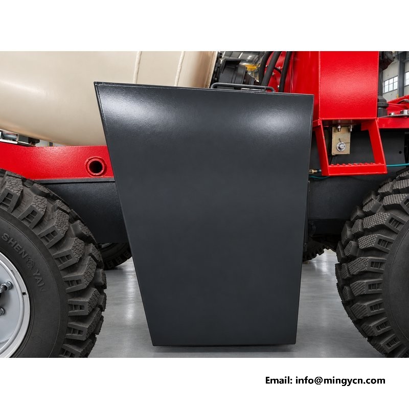
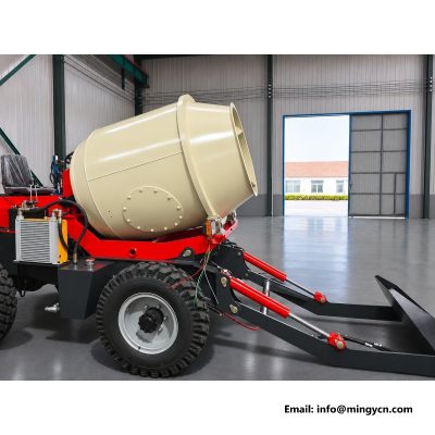
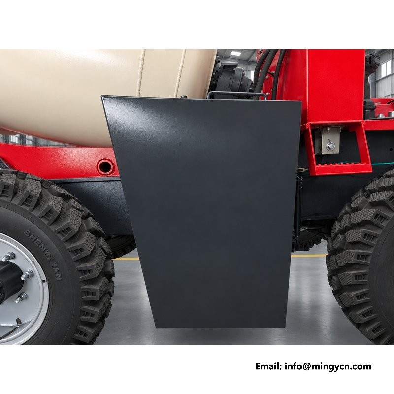
The photographs show the tank mounted to the side and rear of the drum, and that position is a compromise between several competing demands. It keeps the water close to the dosing point, shortens the feed line and leaves the loading shovel and the discharge chute clear at the front. It also has to stay inside the machine's width and clear of the rear 750-16 tyre through the full steering and suspension travel, which is why the inboard face is shaped the way it is. Trace the gap between the tank and the tyre in more than one frame: a clearance that looks generous in one view but closes in another is a rubbing point waiting to happen. Check too that the tank does not block the operator's sight line when reversing or shield a work light.
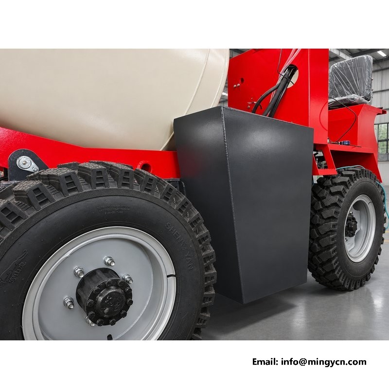
A full tank of water is a shifting, heavy mass carried high and to one side of the machine, and where it sits changes how the mixer behaves long before the drum is loaded. Placing it low and close to the frame, rather than high on the drum, keeps the centre of gravity down and reduces the roll tendency when the machine crosses a cambered yard or turns on a slope. The side mounting does introduce a lateral bias, which is one reason the tank is paired against other fixed equipment and why the tyre pressures and the condition of the steering components matter. In the photographs, judge the height of the tank relative to the axle line and the wheel top. Ask for the machine to be shown on a slope with the tank full, because a static, level photo hides handling traits an operator will feel on the first uneven site.
The fixing points in the close-ups are worth more attention than the tank shell itself, because a sound tank on weak mounts will still crack. Look for brackets that land on welded bosses or gussets on the frame rather than on a flat panel, and for straps or bolts that clamp the tank without crushing the steel. Rubber or composite pads between the tank and the bracket are a good sign: they absorb vibration from the single-cylinder engine and stop a hard edge from fretting through the plate. Count the fixing points from the available angles and check that they are accessible with the machine assembled, since a bolt that cannot be reached with a spanner will not be checked in service. Ask for the tightening sequence and whether the mounts are the same drilled pattern used on a replacement tank.
The square inspection cover visible on the tank is there so the inside can be reached without cutting the shell, and its design tells you how the maker expects the tank to be maintained. A bolted cover with a replaceable gasket can be opened at a service interval to remove sediment, check the internal coating and inspect the baffle welds, while a cover welded shut leaves no route in at all. Look at the corners of the opening: a reinforced ring or folded edge around the cut-out keeps the panel from distorting when the bolts are tightened, and a recessed seat protects the gasket. Ask how often the cover should be opened and what can be seen through it. A buyer who plans to run the machine on hard or silty water will care far more about this cover than a brochure ever suggests.
The broad flat sides of the tank are honest surfaces: they show every weld and every imperfection, which is why these photographs are useful for judging build quality before paint. Look for continuous seams along the folded edges and for corner joints that are sealed on all faces, since a stitch weld on a water tank is a leak waiting for the first vibration. Consistent bead width and the absence of undercut along the plate edge point to controlled settings, while spatter, arc strikes away from the seam and ground-back patches suggest rework. A flat panel also needs stiffening; without it, a large area of plate will drum and flex as water moves, which fatigue-cracks the seams over time. Ask whether the panels are braced internally and how the completed shell was tested for watertightness.
Concrete work is hard on a water tank because the machine is washed down daily and the water is often drawn from a site supply rather than a clean main. Silt and cement fines settle at the low points, where they hold moisture against the steel and start corrosion from the inside, so a drain at the lowest corner and a route to flush the tank are more valuable than a shiny exterior. Ask what internal coating is used and whether it is compatible with potable or site water, and check that the filler screen can be removed for cleaning. In the photographs, look for a drain plug that sits proud of a protected recess rather than one flush with a dirty panel. Establish a rinse and dry routine at the end of each job and leave the inspection cover loose during long storage so the interior can breathe.
A short, repeatable inspection catches most tank faults before they reach the mix. At the start of a shift, check the filler gasket, confirm the cap latches flat, look under the machine for drips at the drain and the feed line, and verify the level or indicator reads sensibly before the first batch. During the day, listen for a pump that runs dry and watch for a dose that no longer matches the display setting, both of which point to a blocked line or a leaking suction. At a longer interval, open the inspection cover, clear sediment from the low points, examine the internal coating for blisters and re-torque the mounting bolts. Write the findings down, because a slow weep that appears every few days is easier to diagnose from a log than from memory.
When a tank or its dosing circuit starts to fail, the signs are usually indirect. A damp patch along a bottom seam, rust streaks below a weld or a white mineral trail beneath the filler all point to a slow leak rather than a spill, and a rising water use with no change in the batch points to a dosing fault. A cap that will not sit flat, a cracked gasket, a loose hose clip and a blocked vent show up as erratic doses or as air drawn into the line. Vibration from the engine can loosen a bracket until the tank rubs the tyre or a frame edge, so treat a new rattle as a fault and not a nuisance. Ask the supplier for the typical failure points on this tank and keep the relevant seals and clips in the spares kit.
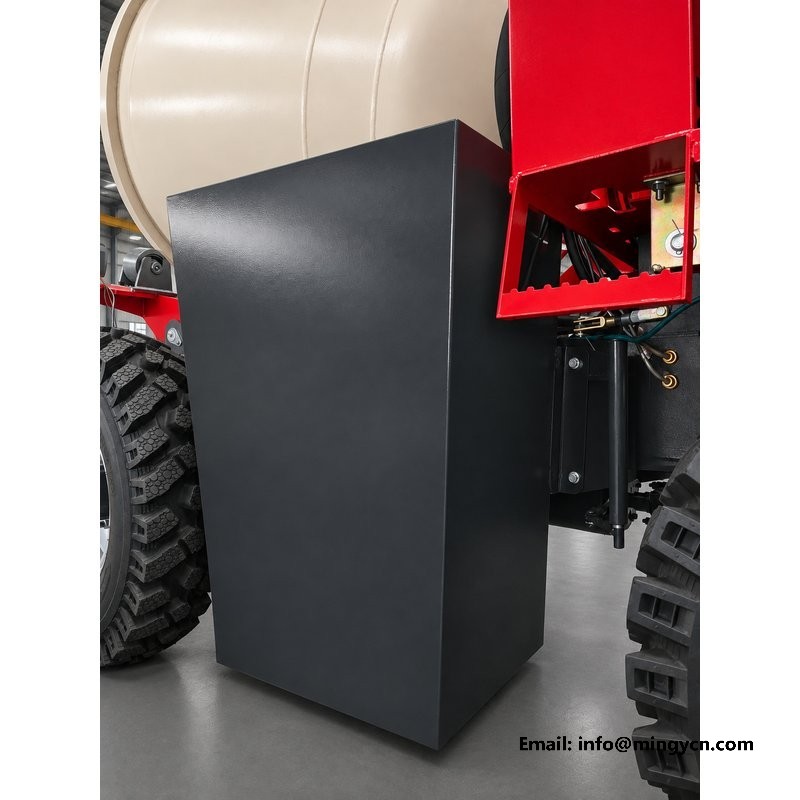
Storage and climate decide how long the tank lasts between jobs. Where frost is possible, standing water left in the shell, the feed line or the dosing valve will expand and split a seam or a fitting, so drain the whole circuit and leave the inspection cover and drain open before a cold shutdown. In hot, dusty conditions, the risk is different: a part-filled warm tank grows algae and holds grit that scores the valve, so keep the cap sealed and the filler screen clean. For a long idle period, drain and dry the interior, coat exposed bare steel at chipped edges, slacken the cap rather than clamp it hard, and park the machine level. Recommission by flushing the tank, checking every gasket and confirming the dose before the first structural pour, not during it. A tank put away clean and dry rarely causes trouble at the start of the next contract.
| 1.5 m³ self loading concrete mixer — on-machine water tank, filler cap, mounting, batching water | |
|---|---|
| Model | 1.5 m³ 4WD self loading concrete mixer |
| Nominal drum capacity | 1.5 m³ (1,500 L) |
| Overall dimensions (L x W x H) | 3,500 x 1,600 x 2,200 mm |
| Front / rear tyres | 750-16 / 750-16 |
Turning circle and gearbox descriptions follow the supplied data sheet; final definitions should be confirmed in the technical file before order.
Water runs from the tank through a feed line to a dosing control at the operator station, so the person at the seat can add it while the drum turns. What matters is repeatability: the same lever or display setting should give the same quantity on consecutive batches, otherwise slump drifts. Check for a protected valve, a routed hose and a level or dose indicator in the photos, and ask how the system is calibrated and drained after a job.
No tank volume is quoted on the supplied data sheet, so none is assumed here. The figures that are published cover the drum, the rated load and the machine, not the auxiliary tank. If an exact volume matters for your dosing or refill planning, request it in the technical file rather than accepting a rounded number from a catalogue. What you can judge from the photographs is the filler, the sealing, the mounting points and the internal access, all of which matter more to daily reliability than a capacity headline.
That position keeps water close to the dosing point, shortens the feed line and leaves the loading shovel and discharge chute clear at the front. It has to stay inside the machine width and clear of the rear 750-16 tyre through the full steering travel, which is why the inboard face is shaped as it is. A full tank carried low and near the frame also keeps the centre of gravity down on cambered ground. Check the tyre gap in more than one photo.
For the current 1.5 m³ self loading concrete mixer specification, engine options and a formal quotation for your market, contact MINGYI Machinery. E-mail: sales@mingycn.com | LINE (ID): mingyicn
Self Loading Concrete Mixer: The Complete Specification · Self Loading Concrete Mixer: What the Specification Really Means · Counterweight Box and Front Structure on the 0.8m3 Self Loading Mixer · Loading Shovel and Lift Arm: Geometry of the Front Loader
More in the 1.5 m³ series: Water Tank Fabrication on the 1.5m3 Mixer: Welds and Baffles · Mixing Blades and Drum Interior on the 1.5m3 Self Loading Mixer · Reversing Camera and Monitor on the 1.5m3 Self Loading Mixer