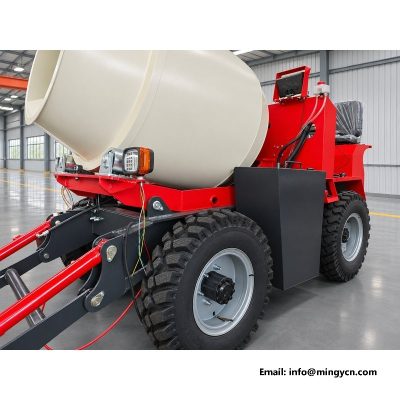
Welded Box-Section Chassis Frame of the 1.5 m3 Self Loading Concrete Mixer with Axle Stations, Lift Arm Bosses and Engine Bed
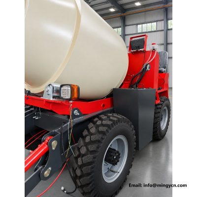
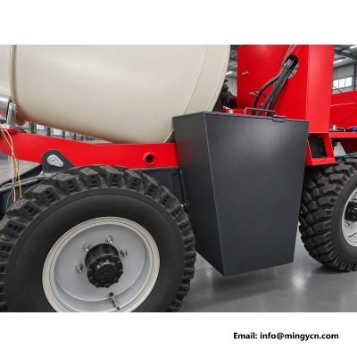
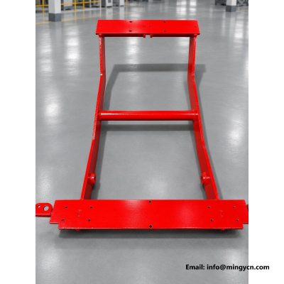
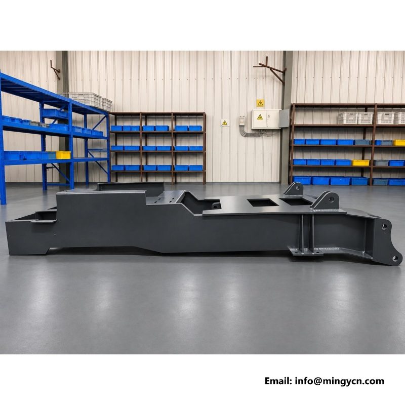
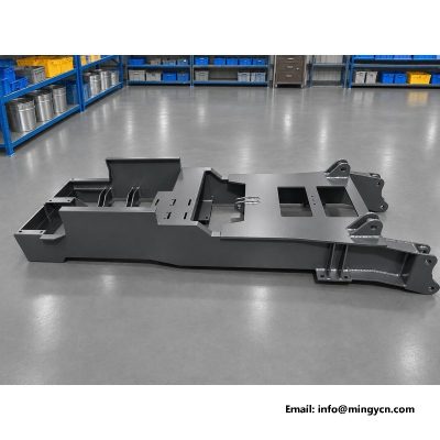
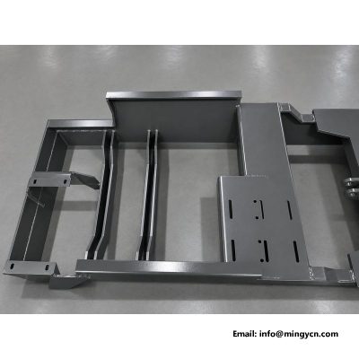
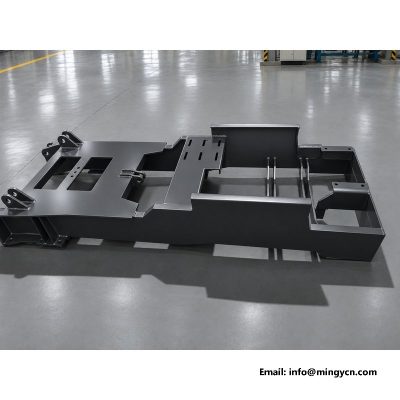
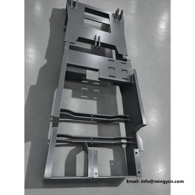
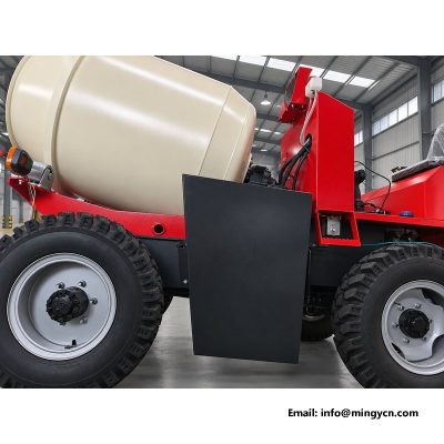
Six photographs on this page show a bare welded frame resting on the workshop floor, with no drum, cab or shovel fitted. That is the stage at which the structure can be judged, because every rail, cross member, axle seat and weld is still exposed. This section explains why the frame uses closed box sections, how the load from a full 1,500 L drum reaches the axles, and what to look for when accepting a fillet weld, a gusset or a lift arm mount bushing. It also covers the engine and water tank mounting holes, the weight-relief cutouts, the checks that belong before paint, and the habits that prevent cracking on rutted ground. Two assembled photographs are included to compare against the finished machine.
The main longitudinal members are closed box sections, and the reason is torsional stiffness rather than appearance. A full batch sits high above the frame, and on rutted ground the front and rear axles are rarely on the same plane, so the rails are continually being twisted between them. A closed section resists that twisting far better than an open channel of similar weight, because the material is distributed all around the section instead of being concentrated on one web. The trade-off is fabrication effort: the ends must be closed, the inside protected against corrosion, and the joints fitted accurately before welding. With a rated load of 5,000 kg and an operating weight of 1,900 kg, the frame has to hold its shape through that repeated loading, since a rail that gradually loses its straightness puts the drum, the axles and the steering geometry out of alignment together.
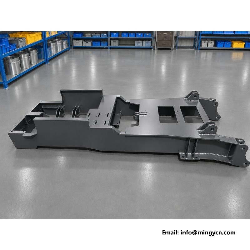
Understanding where the weight goes makes the bare-frame photographs much easier to read. The drum saddle transfers the charge into the two longitudinal rails, cross members spread that load between them, and the axle seats pass it into the Isuzu-type reinforced front axle and the 130 four-wheel steering rear axle, and from there into the 750-16 tyres fitted at both ends. Every one of those handover points is a place where a concentrated force meets a plate, which is why gussets and full-depth cross members appear exactly at the axle stations and under the drum mounts. When reviewing the images, follow that path visually from the top of the frame down to the wheels. A rail that looks continuous but has no cross member beneath a mount is carrying a point load it was never shaped to take, and that is where a crack will eventually start.
Once a coat of paint is on, the weld detail disappears, so the unpainted frames in these photographs are the only practical chance to judge it before the drum is fitted. The principal joints should be continuous fillet runs rather than short stitch beads, with a leg width that stays consistent along the whole length. Look at the starts and stops, since craters and abrupt ends are common fatigue origins, and check that spatter has been removed rather than buried under primer. A sound fillet shows a smooth, even face that merges into both plates without a sharp notch at the toe. Ask the supplier to identify which joints are welded on all faces and which become inaccessible after assembly, because those cannot be inspected later. A photograph of a clean, uninterrupted run is more useful here than any written claim about workmanship, and it is worth requesting for the specific unit being purchased.
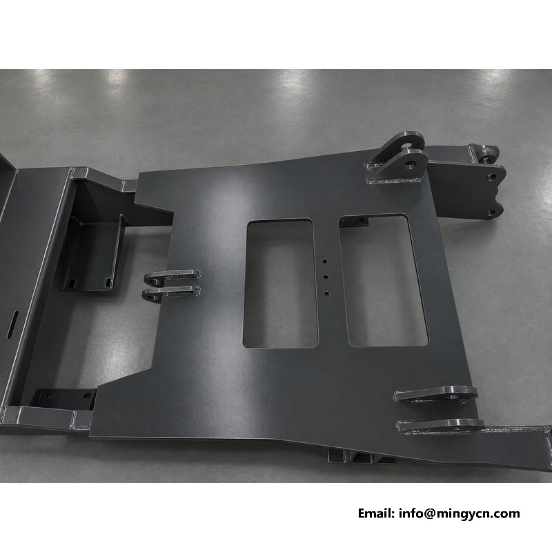
Undercut is a shallow groove melted into the parent plate along the edge of a weld, and it matters because it removes section exactly where stress is already highest. On a chassis that flexes over rough ground, that notch becomes a natural starting point for a fatigue crack. Run a light along the plate edge in the photographs and look for a dark, continuous line hugging the weld toe, or for a weld that appears to sit proud of a thinned plate. Small, isolated marks can be blended by careful grinding, but a long undercut or a cluster of arc strikes calls for re-welding, not filler. Also check for overlap, where weld metal has rolled onto the plate without fusing, and for pinholes in the bead. Catching these on a bare frame is straightforward; finding them after paint and assembly is not, which is precisely the reason to study these images closely.
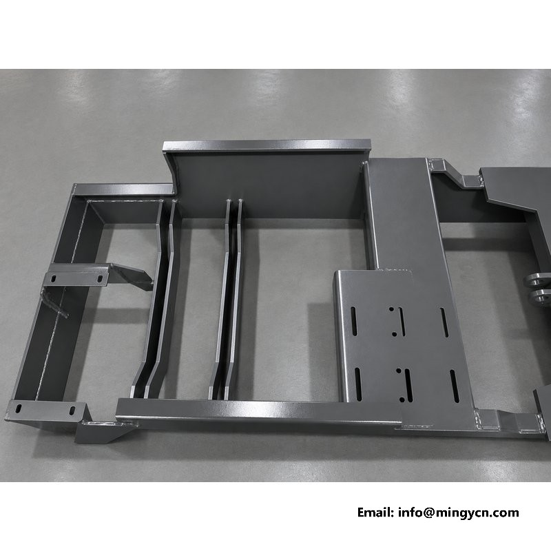
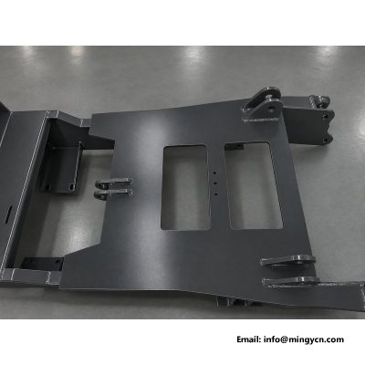
Wherever a bracket meets a rail, the photographs show triangular gusset plates, and their job is to spread a concentrated load along the member instead of letting one small patch of steel absorb it. The lift arm pivots, the engine bed and the drum saddle all apply force at a point; without a gusset, the rail flexes locally at the same spot on every cycle and eventually complains at the weld toe. When reading the images, check that each gusset ties into the rail web and a cross member rather than terminating on a bare flat face, and that its edges are fully welded rather than tacked at the corners. A gusset with a sharp, unblended corner creates a new stress raiser of its own. Properly placed plates are the quiet difference between a frame that stays aligned and one that develops a crack at a weld toe early in its working life.
The lift arm pivots take the sharpest shocks on the machine, because a shovel digging into a stockpile sends its reaction into these mounts before the hydraulics see it. The photographs show heavy bosses welded into the front frame, and the detail worth checking is whether a renewable bushing is pressed into a machined housing rather than the arm running directly on a drilled plate. A replaceable bush means wear is corrected by pressing in a new part, not by cutting the frame open, and a combination of bolting and welding lets the mount be serviced without disturbing the rails. Look for a grease path to the bearing surface and for enough plate around the boss to carry the load into the gussets. A loose or dry pivot announces itself as a knock at full lift, so the fit here is worth confirming at handover while the assembly is still accessible.
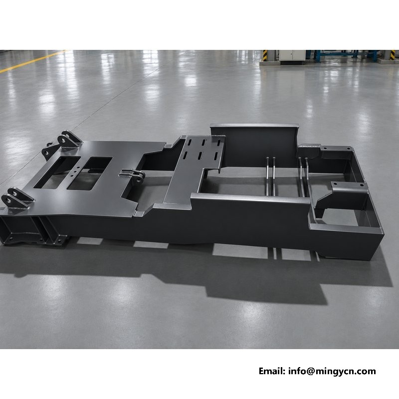
A bare frame also shows the drilled pattern that every bolted component returns to. The engine bed is machined flat for the single-cylinder diesel 25 hp unit with rubber isolators, and tapped or through holes along the rails take the water tank straps, the drum saddle and the shovel frame. Standardised positions matter years later: a replacement engine bed or a new tank lines up with the existing holes instead of being drilled and re-plated in the field. Check that hole edges are deburred, that any plate around a heavily loaded fixing is reinforced, and that the holes are not cut through a weld line. Look also for slotted or oversized holes, which can signal parts being forced into alignment. The whole-machine photographs help here, because they show how the finished assembly sits on the same drilled pattern you are examining bare.
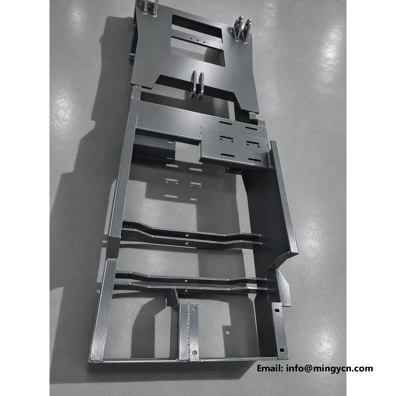
The openings in the side plates are deliberate, and their placement tells you something about how the frame was engineered. Material is removed where bending demand is low, while full depth is kept at the axle seats and under the drum mounts, so the rail stays strong where it is loaded and lighter where it is not. In the photographs, check that each cutout has a rounded corner rather than a sharp inside angle, because a square corner concentrates stress and is a classic origin for a crack. Look at the cut edge quality too: a smooth profile suggests a controlled cut, while ragged, notched edges need grinding before paint. Be sceptical of openings placed close to a bracket or a weld toe, since that removes exactly the section a point load depends on. Read the pattern as a map of where the designer believed the load was highest, and question any opening that contradicts it.
The interval between welding and priming is the last moment when the structure can be inspected as steel, and the photographs on this page capture exactly that window. Before paint, the frame should be cleared of spatter and slag, welds wire-brushed, sharp edges blended, and any undercut or pinhole repaired rather than filled. Check that cavities inside the box sections are sealed and that drain or vent paths are left open, since a closed section that traps water corrodes from the inside. Drilled holes and machined faces should be masked so primer does not change their fit. Ask for the frame identification and the weld inspection record to be photographed alongside the bare unit, so the images can be tied to a specific build. These are the checks that disappear once the drum and cab are fitted, which is why the bare-frame set is worth requesting before any order is confirmed.
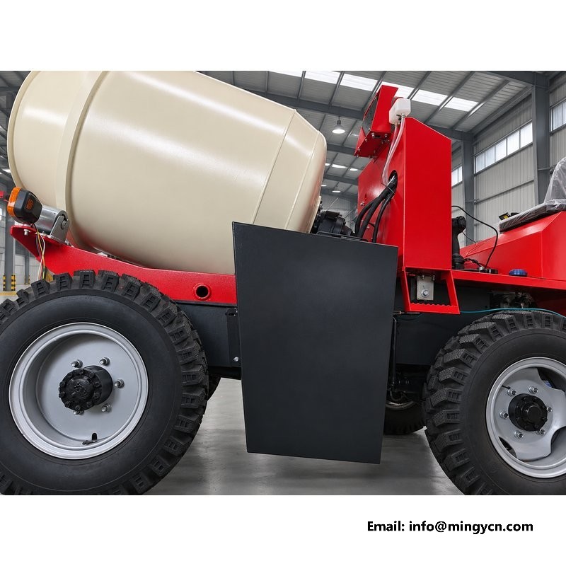
Most frame cracks are fatigue cracks, and they begin at a repeatable short list of places: a weld toe, a cutout corner, a bracket end, or a bushing that has been left dry. The machine cannot avoid rutted ground, but the way it is used changes how fast those points are worked. Keep loads within the 5,000 kg rating, keep tyre condition even across the 750-16 set at both ends so the frame is not held in a permanent twist, and slow down over broken tracks instead of crossing them at the 24 km/h maximum travel speed. Re-tension mount fasteners on a routine, and deal with a hairline mark when it is still a mark, by cleaning, drilling a stop at its end where appropriate, and re-welding properly. A small repair done early is contained; the same crack after a season reaches the rail web and becomes a structural job.
The axle seats are welded to the frame, so their relative position fixes the steering behaviour of the finished machine. The Isuzu-type reinforced front axle and the 130 four-wheel steering rear axle have to sit parallel and square to the rails; a weld that pulls a seat out of line will show up as uneven tyre wear and a machine that pulls to one side. A steering angle of 28 degrees and a turning circle at the outer tyre edge of 2,464 mm depend on that alignment, as does the behaviour of the four-wheel-drive gearbox with three forward and one reverse plus road gear when the machine is manoeuvred under load. The published turning circle and gear wording follows the supplied data sheet and should be read alongside the technical file rather than assumed. In the photographs, look for full-depth cross members at the seats and for a weld sequence that would hold distortion down.
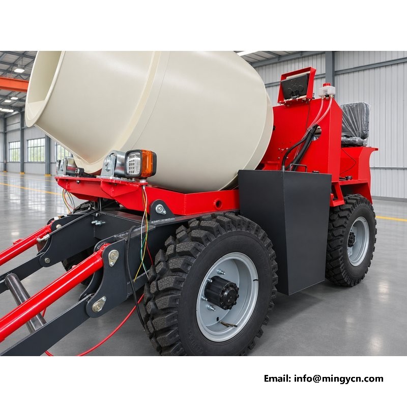
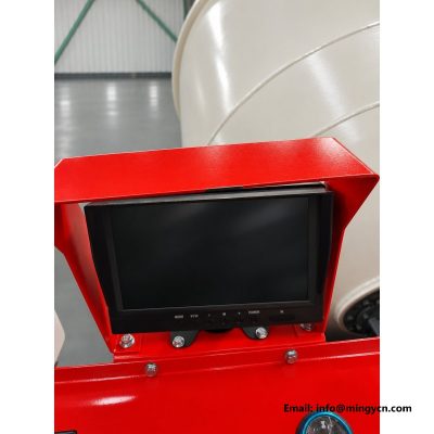
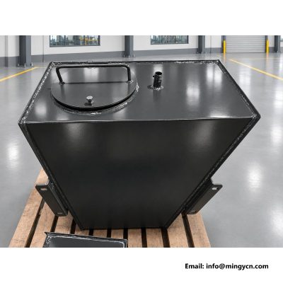
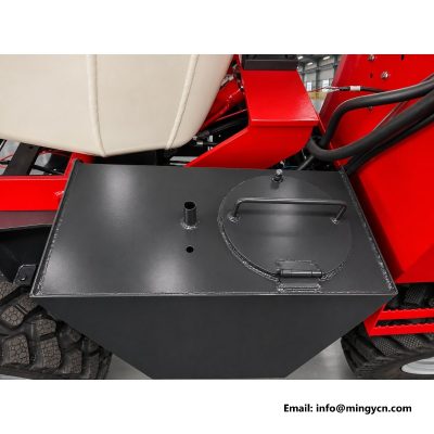
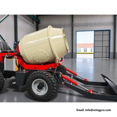
Six images show the grey welded frame lying on the workshop floor and on pallets with nothing fitted, which is the most useful condition for judging structure. Read them in order: follow the box-section longitudinal rails, then the cross members, then the axle seats, the lift arm pivot bosses, the cutouts, the gusset plates and finally the continuous fillet welds that join everything. Because the drum, cab and shovel are absent, nothing hides a thin plate, a skipped weld or a bracket set on a bare face. Compare the same details across several frames if the supplier has more than one unit in the batch, since consistency tells you more than a single good example. The two assembled photographs are there to place those bare-frame features back on the finished machine, so you can confirm that what you approved is what actually gets delivered.
| 1.5 m³ self loading concrete mixer — bare welded chassis, frame rails, axle mounts, structural lo | |
|---|---|
| Model | 1.5 m³ 4WD self loading concrete mixer |
| Operating weight | 1,900 kg |
| Overall dimensions (L x W x H) | 3,500 x 1,600 x 2,200 mm |
| Front axle | Isuzu-type reinforced front axle |
Turning circle and gearbox descriptions follow the supplied data sheet; final definitions should be confirmed in the technical file before order.
Because paint and assembly conceal the details that determine how long a chassis lasts. With the drum, cab or shovel removed, the rail sections, cross members, gussets, axle seats and weld runs are all visible for comparison. It is the one point in production when undercut, skipped welds or a thin bracket can still be corrected without dismantling a finished machine. A buyer should ask for these images with the frame identification included, so they can be tied to the actual unit being purchased.
Undercut along a plate edge, inconsistent leg width, abrupt starts and stops, overlap where metal has rolled onto the plate without fusing, and pinholes in the bead are the ones to look for. Each either removes section or creates a notch at a point that is already carrying high stress, and repeated flexing over rough ground turns that notch into a crack. Judge these on the unpainted frame, since paint hides the detail you need to see.
Often yes, provided the crack has not spread into the rail web. The repair should remove the affected weld, address whatever concentrated the load in the first place, and reinstate the gusset and the bushing housing to the original geometry rather than welding over the mark. A renewable bushed mount makes this straightforward; welded-solid pivots are far harder to restore. Ask for the repair procedure, and treat any repeat crack as evidence that the load path, not the weld, needs redesigning.
For the current 1.5 m³ self loading concrete mixer specification, engine options and a formal quotation for your market, contact MINGYI Machinery. E-mail: sales@mingycn.com | LINE (ID): mingyicn
0.8m3 Self Loading Mixer Chassis: Frame Rails and Lift Arm Mounts · Driveshafts, Differentials and Axle Housings on the 0.8m3 4WD Mixer · Reinforced Axle 0.8m3 Self Loading Mixer for Unpaved Sites · Loading Shovel and Lift Arm: Geometry of the Front Loader
More in the 1.5 m³ series: Roll Bar and Operator Guard on the 1.5m3 Self Loading Mixer · 750-16 Tyres and Isuzu Front Axle on the 1.5m3 Mixer · 1.5m3 Mixer Dimensions: 3500 mm Body, 2464 mm Turning Circle