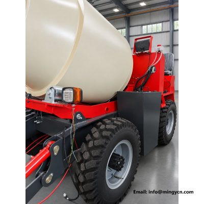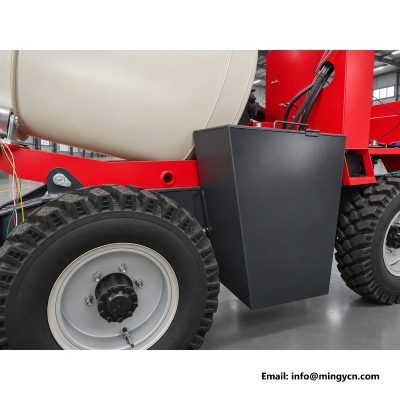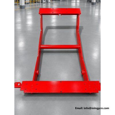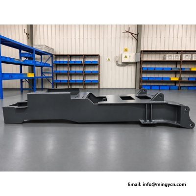
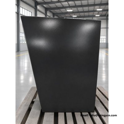
Fabricated Steel Water Tank for the 1.5 m3 Self Loading Mixer Showing Seam Welds, Internal Baffles, Lifting Handles and Pallet Handling
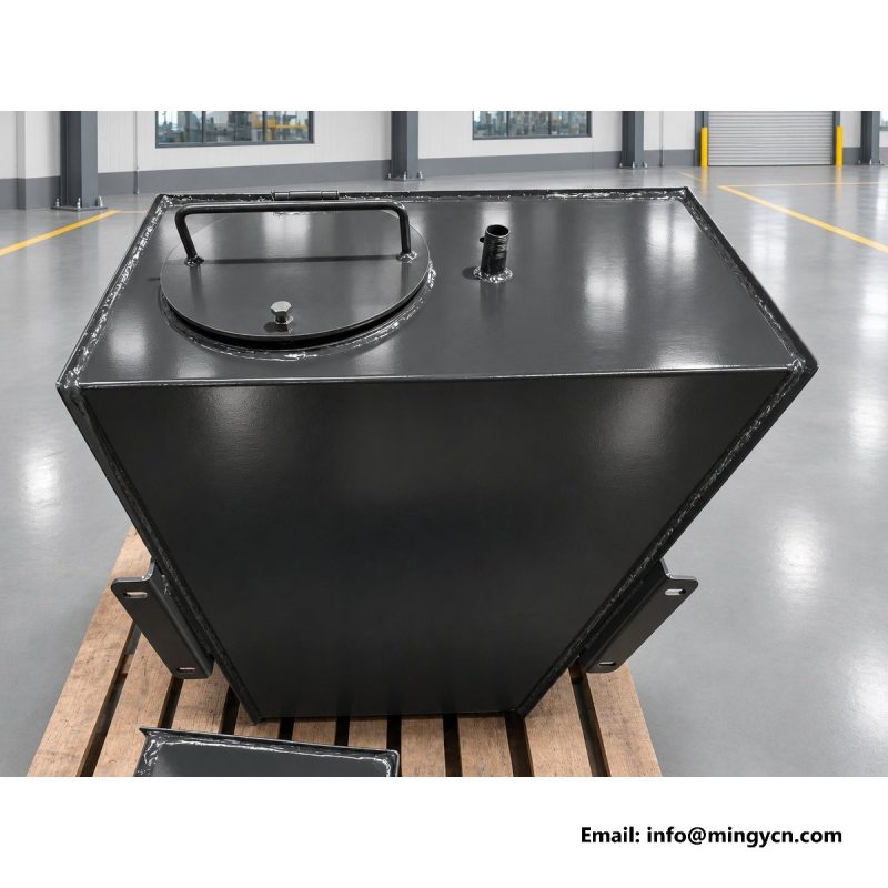
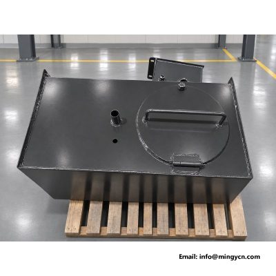
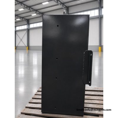
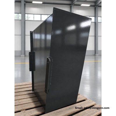
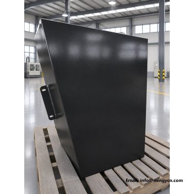
Before it is bolted to a chassis, the water tank is a freestanding fabricated assembly, and the photographs show it resting on a wooden pallet, unpainted. With the machine stripped away, the continuous weld runs, the internal baffle outline, the lifting handles, the filler flange, the square inspection cover, the bottom support feet and the bare steel plate are visible at once. This page reads that fabrication: how the plate is cut and folded, what a sound weld looks like, why baffles are fitted inside a tank, how the unit is moved by forklift, what preparation it receives before coating, and how a spare tank should be checked against the original bolt pattern. It is written for buyers taking delivery of a replacement tank or auditing a supplier's welding.
An unpainted tank sitting on a wooden pallet is the most informative version of the part a buyer will ever see, and these photographs use exactly that condition. With no machine around it and no coating to hide the steel, the continuous weld runs, the folded corners, the filler flange, the square inspection cover, the lifting handles, the bottom feet and the internal baffle outline are all readable at once. Treat the set as an inspection record rather than a product shot. Start at the corners, where the most stress concentrates, then follow each seam along its full length. A supplier willing to photograph the part in this state is usually one with nothing to conceal in the weld quality, which is why the bare condition is worth requesting before an order is placed. Ask for the set to be dated and kept with the build record, so the exact unit shipped can be matched to its welds later.
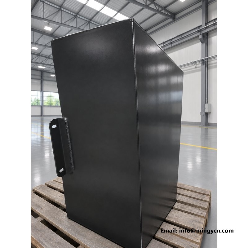
Before any welding, the shell is a set of flat steel blanks cut and folded to shape, and the photographs of the bare plate show what that preparation looked like. Clean cut edges, square corners and consistent fold radii mean the parts met in the jig without being forced, which is the precondition for a watertight seam. Look for tack marks or temporary cleats in the images; they reveal how the panels were held in position before the final runs. A trapezoidal tank needs its sloped panel and its sides to share a common datum, otherwise the filler flange and the mounting feet drift out of line and the tank will not sit flat on the frame. Ask what cutting method was used and whether the blanks were deburred, since a rough edge left under a weld is a common start point for a crack.
On a fabricated water tank the seams are the product, because the plate itself rarely fails. The photographs show continuous runs along the folded edges, and that is exactly what a buyer should expect: an unbroken bead with a consistent leg width, a smooth tie-in at the corners and no visible start or stop craters in the middle of a run. Stitch welds, scattered arc strikes, spatter left on the plate and heavy grinding that thins the parent metal are all signs of a rushed job. Pay particular attention to where a bracket, a handle or a flange lands on a seam, since those overlapping joints concentrate load. Ask how the finished shell was pressure tested and whether the welds were examined before priming, because a pinhole under paint only announces itself after the tank is fitted and filled.
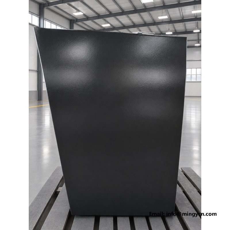
The faint outline of internal baffles visible through the open shell is not decoration; it is what stops a part-filled tank from slamming its contents from one end to the other as the machine moves. A mixer brakes, climbs ramps and turns with water on board, and an undivided volume lets that mass surge, loading the end panels and the mounting brackets with a force far greater than its static weight. Baffles break the space into connected compartments so the water still equalises but cannot accelerate as one body. They also stiffen the broad flat sides, which otherwise flex and fatigue the seams. In the photographs, trace where the baffle edges meet the shell and check they are welded on both faces with a drain path left at the bottom, so no pocket traps sediment or standing water.
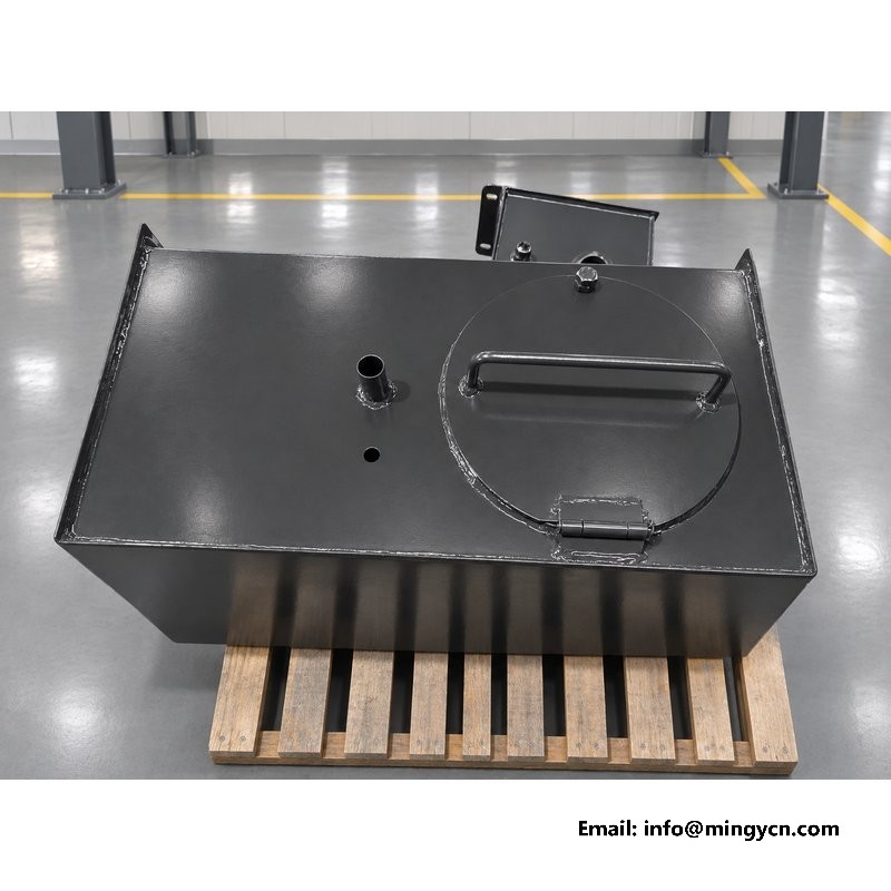
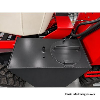
Two openings define how the tank is filled and serviced, and both are visible as separate fabricated parts in the pallet photographs. The filler flange is a raised ring welded around the neck, stiffening the hole and giving the cap gasket a flat, protected seat; a flange welded only on one face or ground flush with the panel will distort and leak. The square inspection cover is larger, and its corners are the likely place for a crack to start, so look for a reinforced rim and a bolt pattern that clamps evenly rather than a few scattered fasteners. Check that both openings are positioned where a gloved operator can reach them once the tank is mounted. Ask whether the cover gasket and the filler gasket are the same replaceable stock item, which simplifies the spares list considerably.
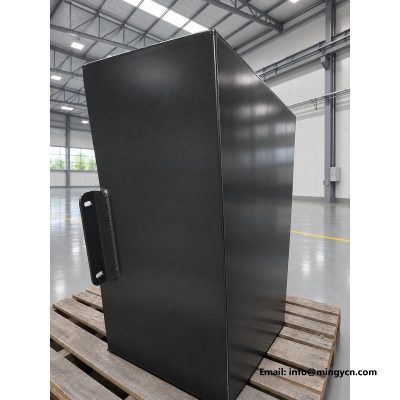
The lifting handles and the bottom feet are small details that decide whether the tank survives the journey from the workshop to the chassis and, later, a replacement in the field. Handles should be welded to a reinforced pad or a stiffened section of the shell, never to a single unsupported panel that will tear when a sling takes the weight. The feet set the tank on the pallet and later on the frame, so they must sit in one plane; a twisted foot rocks the shell and preloads the mounting bolts before any water is added. Look at the photographs for clean welds all round each handle and for feet that align with the folded edges. Ask for the lifting points to be marked and for a rated slinging method, since an ad-hoc lift is a common source of a dented or distorted spare.
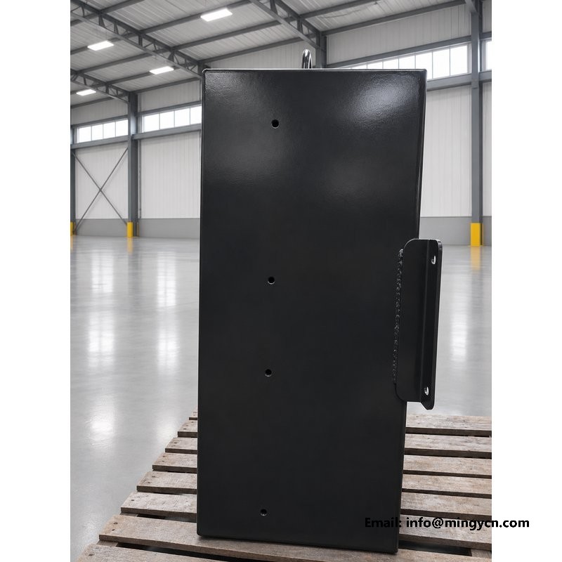
Once the shell is welded and before any primer goes on is the only point at which the seams can be judged honestly, and a buyer should ask for that exact stage to be photographed. A buyer can ask for a simple visual record: full-length shots of each seam, close views of the corner tie-ins and of every nozzle or bracket weld. Beyond appearance, ask whether the maker flood-tests or pressure-tests the closed tank and whether dye penetrant is used on the critical joints. Pinholes, undercut and lack of fusion do not show in a finished, painted machine, and a leak that appears after delivery is expensive to argue about because the tank has to come off the frame to be repaired. Agree the acceptance standard and the test record in writing, and link them to the serial number of the tank being supplied.
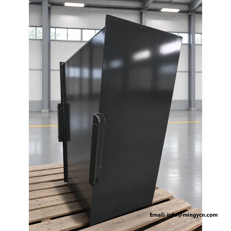
The wooden pallet in these photographs is part of the manufacturing story, not just packaging. A fabricated tank of this size is moved by forklift from the welding bay to the paint bay and then to the assembly line, so the feet and the pallet need to present clear fork pockets and a stable, level load. Look at how the tank sits: it should bear on the feet rather than on a folded seam or a protruding flange, and the centre of mass should sit well inside the pallet footprint so a turn does not tip it. Ask whether lifting is done with a sling through the marked handles or by fork under the pallet, and how the shell is protected from chain and fork damage. A dent sustained in handling is often the origin of a coating failure and a rust spot years later.
The bare steel in the photographs is the last view anyone has of the plate before the coating system is applied, and that system decides the tank's working life. Blast cleaning or mechanical preparation removes mill scale and weld oxide; primer then has to reach into the seam toes, the bracket corners and the inside of the filler neck, all of which are easy to miss on a spray pass. Ask what is used on the interior as well as the exterior, since the inside sees standing water and silt while the outside sees wash-down grit and sunlight. A buyer should request the coating specification by name and the dry film target, and confirm that the inside is coated before the inspection cover is closed. Chips at the feet and the handles should be touched up before the tank is bolted to a chassis.
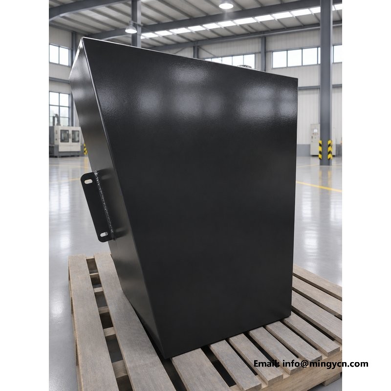
A replacement tank is only a true spare if it bolts to the machine without drilling, shimming or re-routing the feed line. When you order one, compare the mounting foot positions, the filler and inspection cover locations and the feed connection against the original, using the bare-part photographs as a reference. Ask for the bolt pattern and the thread specification in writing, and confirm that the handles, brackets and gasket seats are identical to the fitted unit. A visually similar tank with a shifted flange can foul the tyre or the drum once installed, and a changed outlet height can leave air in the dosing line. Take delivery of the spare in the same bare or primed condition shown here, so the welds can be inspected before it disappears into stores and is forgotten until a failure.
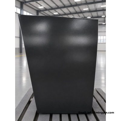
Thin sheet and long seams invite two problems that the bare photographs make visible: distortion and small leaks. Heat from continuous welding pulls a flat panel out of shape, so a tank that rocked on its pallet or shows a wavy side is one that will also preload its mounts and stress the corner joints. Grinding a seam back to hide a bad bead thins the metal and often opens a pinhole that only appears under a water test. Look closely for filler or body-smoothing compound near a weld, for a panel that has been heated and quenched, and for a seam that suddenly changes width. Ask the maker to point out any rework on the photographed unit and to state whether the shell was re-tested afterwards, because undocumented repairs are the ones that fail in service. A short dye check at this stage is cheaper than any field repair.
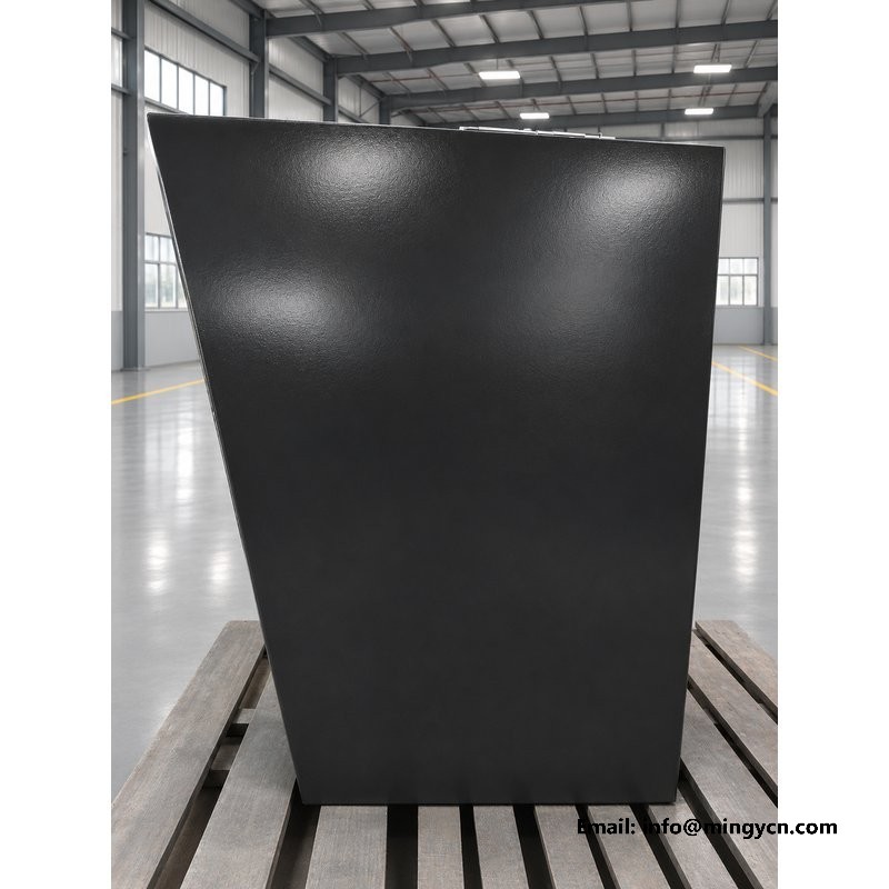
Close the loop by writing down what a good tank looks like before one is accepted, whether it is the original build or a spare. The list should cover continuous, even welds with clean corner tie-ins, a flat mounting plane across the feet, a filler flange and inspection cover that seat their gaskets without force, baffles welded on both faces with a drain path, marked lifting points, an interior coating that reaches the seam toes, and a documented leak test tied to the unit. Compare each delivered tank against the bare photographs and against the original bolt pattern. Reject a unit that needs a hammer to line up its holes, since a forced fit is a crack waiting to develop. Keep the inspection record with the machine file so the next buyer of a spare has the same reference.
| 1.5 m³ self loading concrete mixer — tank fabrication, weld quality, standalone component, spare | |
|---|---|
| Model | 1.5 m³ 4WD self loading concrete mixer |
| Nominal drum capacity | 1.5 m³ (1,500 L) |
| Overall dimensions (L x W x H) | 3,500 x 1,600 x 2,200 mm |
| Engine | Single-cylinder diesel, 25 hp |
Turning circle and gearbox descriptions follow the supplied data sheet; final definitions should be confirmed in the technical file before order.
Baffles stop a part-filled tank from throwing its water from one end to the other as the mixer brakes, climbs and turns. Without them the moving mass loads the end panels and mounting brackets well beyond its static weight, and the broad flat sides flex until the seams fatigue. They also stiffen the shell. In the bare photos, check that baffle edges are welded on both faces and that a drain path is left at the bottom so no pocket traps sediment or standing water.
Judge the seams in the unpainted state, because primer hides undercut and pinholes. Ask for full-length shots of each weld, close views of corner tie-ins and of every bracket or nozzle joint, plus the leak-test record. Look for continuous beads with even leg width, no stitch runs, no spatter and no heavy grinding that thins the plate. Agree the visual and test acceptance standard in writing and tie it to the serial number of the tank you are buying.
Only if the mounting foot positions, the filler and cover locations and the feed connection match the original. Ask for the bolt pattern and thread specification in writing, and confirm the handles, brackets and gasket seats are identical. A visually similar tank with a shifted flange can foul the tyre or the drum, and a changed outlet height can leave air in the dosing line. Reject any unit that needs a hammer to line up its holes, and keep the inspection record with the machine file.
For the current 1.5 m³ self loading concrete mixer specification, engine options and a formal quotation for your market, contact MINGYI Machinery. E-mail: sales@mingycn.com | LINE (ID): mingyicn
Paint, Steel and Finish: Build Quality on the 0.8m3 Mixer · 0.8m3 Self Loading Mixer Chassis: Frame Rails and Lift Arm Mounts · Export Standard Self Loading Mixer: Shipping and Commissioning · Delivery Photos: The 0.8m3 Mixer Before Loading and Shipment
More in the 1.5 m³ series: Mixing Blades and Drum Interior on the 1.5m3 Self Loading Mixer · Reversing Camera and Monitor on the 1.5m3 Self Loading Mixer · Welded Chassis Frame on the 1.5m3 Self Loading Mixer