Red Steel Roll Bar and Operator Guard Frame on the 1.5 m3 Self Loading Concrete Mixer, Bolted to the Rear Deck
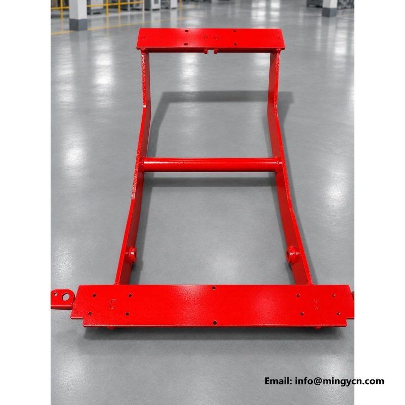
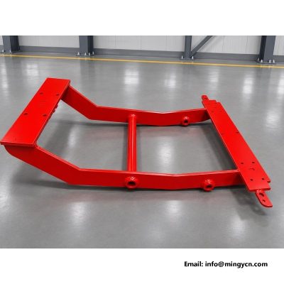
This page covers the roll bar and operator guard supplied with the 1.5 m3 self loading mixer, shown as bare red steel frames photographed on the workshop floor before they are fitted. With no drum, cab or load in the way, the rectangular tube sections, the middle cross brace, the drilled base plates, the welds and the paint finish are all open to inspection. The notes below follow the order a buyer uses at handover: what the structure protects, how its load path works, what to check at the welds and mounting faces, how it affects the view from the seat, how the finish resists corrosion, and what to inspect daily and after transport.
A roll bar and the operator guard around it exist to keep a clear space around the driver, not to carry a load. On a self loading mixer the operator sits beside a turning drum, a shovel that swings overhead and a water tank that shifts the balance as it empties, so the guard defines a protected envelope those moving parts should not enter. The photographs show the bare red steel frames standing alone on the workshop floor before they are bolted to a chassis, the one stage where every post, cross brace and base plate can be seen from all sides. Read them as a buyer reads an inspection report: look for a structure that surrounds the operator position, ties into the frame at several mounting points and leaves room to reach the controls without leaning past a post. It is a passive structure, so judge the steel and the joints rather than a rating.
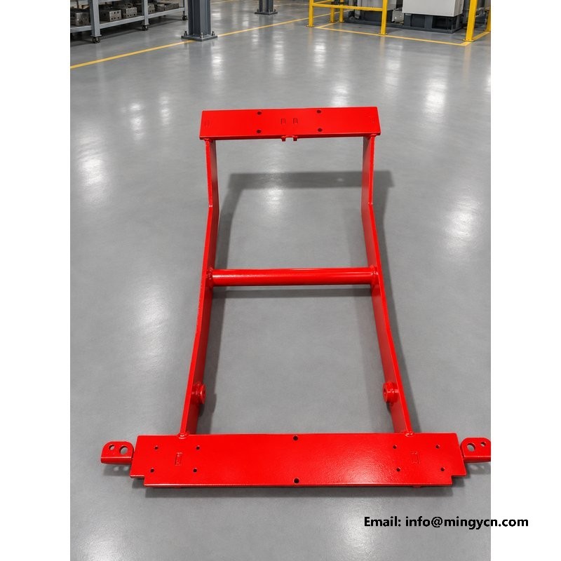
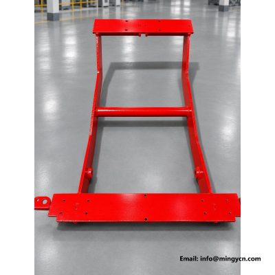
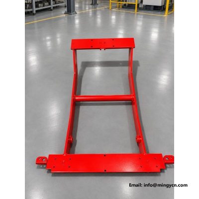
Rectangular tube is used here because a closed section resists twisting better than a flat bar or an open channel of the same weight, and a guard that racks sideways has already failed at its job. In the photographs, follow each upright from its base plate up to the top rail and note where the middle cross brace ties the posts together; that is the basic ladder you are buying. Because the frames are photographed from several angles on the floor, you can check that the corners are square, the tube ends are properly closed, and the members line up without a visible twist. Look closely at the inside faces and undersides, the areas hardest to paint and easiest to skip on a rushed frame. A frame that looks clean from every angle is usually one built on a jig, which is worth more than a heavy coat of paint.
One question the side views answer is why the cross brace is placed partway up the posts rather than at the top or the bottom. Its job is to stop the frame folding into a parallelogram under a sideways load: without it, two uprights joined only at their feet behave like a gate and lean together; with it, the load is shared between the posts and passed into both base plates. The height is a compromise between stiffness and the space the operator needs to see and move through, set where it braces the widest unsupported span without crossing the main sight line from the seat. When you compare the angles in the photographs, check that the brace lands on the post faces with full contact and is welded all round rather than just tacked. A brace that meets the post on a gap will work loose under vibration long before the steel itself is tired.
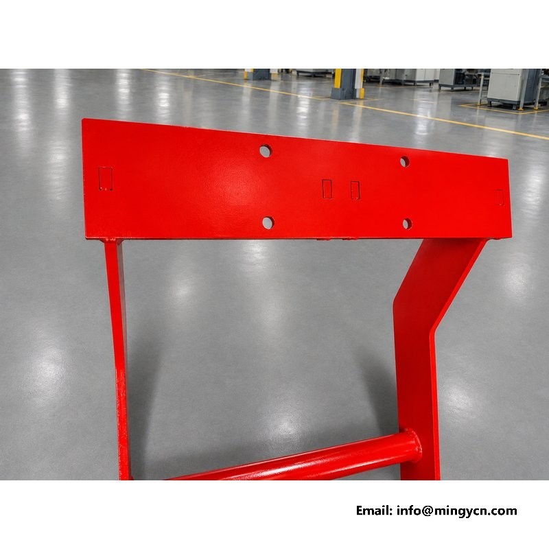
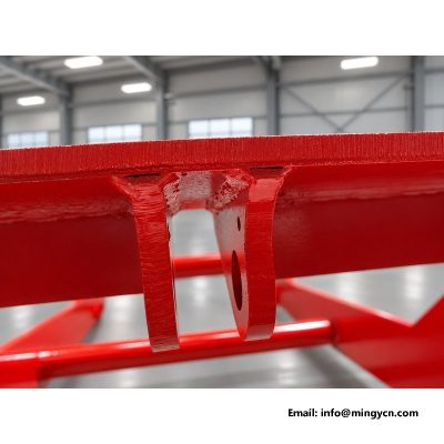
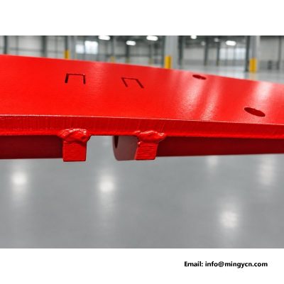
Welds are the part of a guard you can judge properly only before it is painted and fitted, which is why these bare frames are useful. Work along each joint and look for a continuous, even bead: a steady width, no undercut biting into the tube wall at the toe, no pinholes or crater cracks where the arc stopped, and no spatter left where paint will later lift. The joints that matter most are where uprights meet base plates and where the cross brace meets the posts, because those take the shock of a knock and the constant vibration of a diesel machine. A gusset at the post foot is a good sign, since it spreads that working load along the plate instead of concentrating it under one weld toe. Record anything doubtful with a photograph before acceptance; a weld hidden by paint is a weld you will not see again until it cracks.
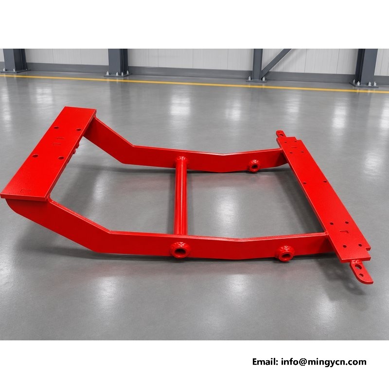
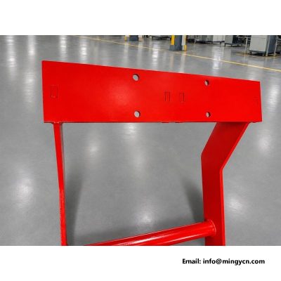
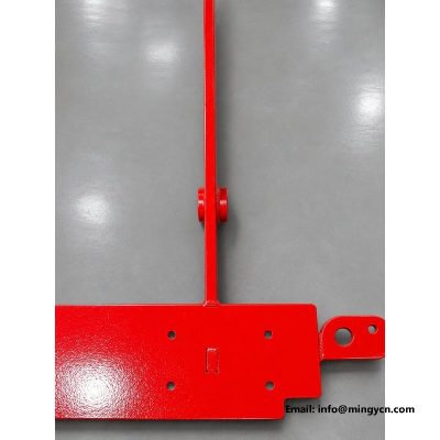
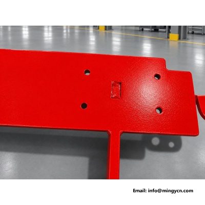
The base plates are the interface between the guard and the chassis, so treat their bolt holes as a fit check rather than a formality. In the close views you can see that each plate is drilled through and sits flat; the things to verify are that the holes are round rather than ovalised, clean of weld spatter and burrs, and spaced to match the welded pads on the frame without needing a drift pin to persuade them into line. A plate that has been pulled down onto an uneven pad will rock, and a rocking plate will work its bolts loose. Check that the underside is flat and that the tube meets the plate with full contact all the way round. At handover, offer the frame up dry first, confirm every hole aligns freely, and only then fit and tighten the fasteners. Forcing a bolt through a misaligned hole is the start of most loose-guard complaints.
A guard that protects the seat but hides the work is a poor trade, so check the sight lines from the driving position, not from the workshop floor. The mixer asks the operator to watch the drum mouth while loading, the shovel edge while digging and the ground in front of the wheels while reversing, and each of those is a low or forward view that an upright or a rail can interrupt. In the photographs, imagine the seated eye position and trace what the top rail and the cross brace would cut off; the posts should sit outside those cones or be narrow enough to look past. Mirrors help, but they are an aid, not a cure for a badly placed bar. If a member sits across a key view, raise it with the supplier before the frame is painted, when a change is still inexpensive and the chassis pads can be moved.
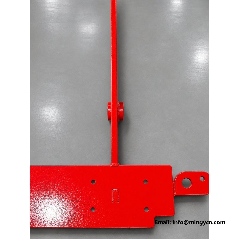
Climbing in and out is where a guard proves whether it was designed around a person or just around a drawing. The frame sets the width of the entry gap and the height at which a cross brace has to be ducked under, so look at the photographs and ask which side the operator is expected to use, where the step and the handhold fall, and whether a boot or a sleeve is likely to catch on a bracket or a protruding bolt head. Three points of contact are the habit to protect, and a guard that forces a twist or a jump works against that. Check too that the entry stays clear when the shovel is raised and the drum is turning, since the machine is often boarded mid-cycle. Smooth tube ends and rounded bracket edges are worth more here than extra steel, and they are simple to call out at the start.
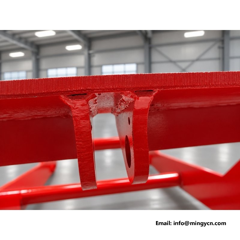
The red finish is doing real work on a machine that lives outdoors on wet, muddy sites, so read it as a corrosion system and not as decoration. In the photographs the paint should cover the tube ends, the inside faces and the weld toes, which are exactly the places a spray gun misses and rust starts first. Look for bare steel around the drilled bolt holes, for spatter that has been painted over and will flake, and for any sign that the plate edges were left sharp, since paint thins on a sharp edge. Ask whether the frames were primed before the top coat and how the inside of the closed tube is protected, because water that gets into an unsealed section works from the inside out. Plan to touch up any chip at the weld toes promptly, and keep a note of the paint used so a repair matches rather than standing out.
The guard needs a few seconds of the same walkaround that the tyres and hoses get before the first batch. Start at the base plates and look for a fresh rust trail or a gap opening between the plate and its pad, both of which point to a bolt that has started to move. Run your eye up each upright to the weld toes for a hairline crack, then across the cross brace for a bend or a dent left by a shovel or a branch. Mark the position of the bolt heads with a paint line so a loose one is obvious at a glance, and check that no fastener is missing after transport. A guard is a passive structure, so it gives no warning before it is needed; the walkaround is the only feedback you get. Keep the checks brief but consistent, and act on a mark that has shifted rather than adding it to a list.
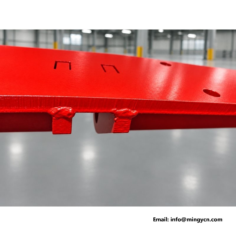
Height is often the reason a guard comes off: with the frame in place the machine stands at the published 2,200 mm, and removing it can lower a load enough to suit a container or a low trailer. Treat that as a planned job rather than a shortcut at the loading bay. Label each frame and bag its bolts with the frame it came from, protect the painted faces and the threads during the move, and cap the open holes on the chassis pads so grit stays out. On refitting, offer the plates up dry, start every bolt by hand and tighten them evenly in a cross sequence so the plate pulls down flat instead of cocking. Recheck the sight lines and the entry gap afterwards, because a frame forced onto a misaligned pad will sit differently from how it left the factory. Record the removal in the handover notes.
The failures a guard actually develops are rarely dramatic. The usual first sign is a hairline crack at the toe of a post-to-base-plate weld, where vibration and a small amount of movement concentrate over time; the second is a bolt hole that has gone oval because a loose fastener was left to hammer. Rust blisters at a weld toe, a cross brace bent by a knock from the shovel, flaking paint on an inside face and a missing bolt after a long trip all belong on the same list. None of these stop the mixer from turning a batch, which is why they get missed. Catch them early and the repair is a weld, a bolt or a touch-up; leave them and the frame has to be cut off and replaced. Photograph the area and compare it at the next service, so a slow change is visible rather than surprising.
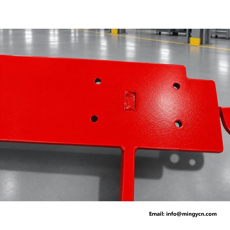
Not every pour needs a guard, so decide from the ground and the way the machine will be worked. It earns its place on sloping or rutted sites, under overhead loading, along tracks with low branches, on embankments where a wheel can drop, and anywhere one operator works alone with the shovel cycling overhead. On a flat, open yard with a clear loading line it adds less, though it still protects against a dropped scoop or a swinging load. Ask for it with the machine rather than as a later addition, because the chassis pads and the bolt pattern have to be there from the start. Do not treat it as a substitute for level ground, a sensible speed on the 24 km/h machine or a careful operator; it is the last line, not the first, and it is most useful on a site that is already being run sensibly.
| 1.5 m³ self loading concrete mixer — roll bar, operator protection, guard frame, site safety | |
|---|---|
| Model | 1.5 m³ 4WD self loading concrete mixer |
| Operating weight | 1,900 kg |
| Overall dimensions (L x W x H) | 3,500 x 1,600 x 2,200 mm |
| Steering angle | 28° |
Turning circle and gearbox descriptions follow the supplied data sheet; final definitions should be confirmed in the technical file before order.
On the machine shown, the guard is a bolt-on assembly: the photographs show the base plates already drilled and the frames freestanding on the workshop floor, so it is shipped as a separate structure and fixed to pads on the chassis at handover or after transport. That is useful to know when you plan delivery, because the crate and the fitting bolts travel with the machine, and the guard may be removed again to reduce height for a container. Ask the supplier to mark which pads each frame lands on.
Look for a continuous bead along each joint rather than short stitch runs, an even width with no obvious undercut where the weld meets the plate, and no crater cracks at the points where a run starts or stops. Pay most attention to the post-to-base-plate joints and the ends of the middle cross brace, because those carry the sharpest loads. Spatter and rough toes are cosmetic; a visible crack or a plate that has lifted from the base is not. Photograph anything doubtful before acceptance.
It can, so check it from the seated position rather than from the ground. The uprights and the top rail should sit outside the forward and downward sight lines you use to watch the drum mouth, the shovel edge and the ground in front of the wheels. The middle cross brace is the part most likely to cut across a mirror or a low sight line. If a post sits in the way, that is a layout issue to raise before fitting, not something to accept and work around.
For the current 1.5 m³ self loading concrete mixer specification, engine options and a formal quotation for your market, contact MINGYI Machinery. E-mail: sales@mingycn.com | LINE (ID): mingyicn
Easy Operation Self Loader: One Operator, Full Cycle · 0.8m3 4WD Self Loading Mixer with Operator Cab: Weather Protection · Single Operator 0.8m3 Concrete Mixer: The One-Person Loop · The 0.8m3 Mixer in the Yard: Whole-Machine Photos and What They Show
More in the 1.5 m³ series: 750-16 Tyres and Isuzu Front Axle on the 1.5m3 Mixer · 1.5m3 Mixer Dimensions: 3500 mm Body, 2464 mm Turning Circle · 1.5 m3 Self Loading Concrete Mixer: Full Specification and Walkaround