Measured Dimensions of the 1.5 m3 Self Loading Concrete Mixer: 3500 x 1600 x 2200 mm, 204 mm Clearance, 28 Degree Steering and 2464 mm Turning Circle
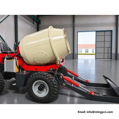
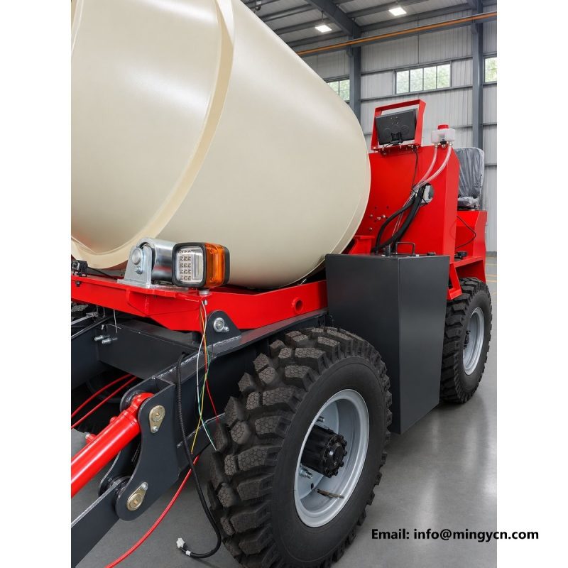
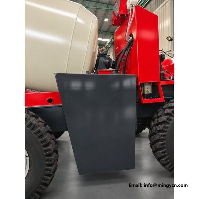
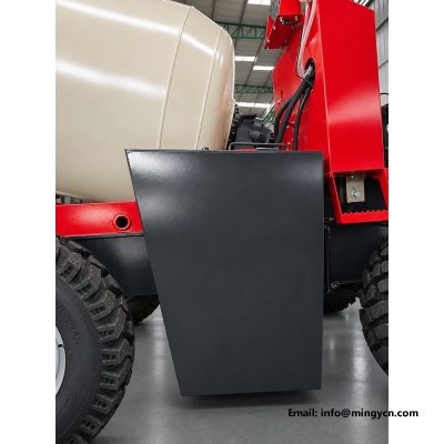
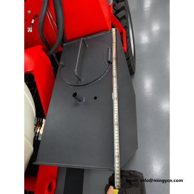
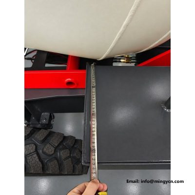
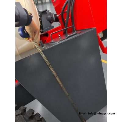
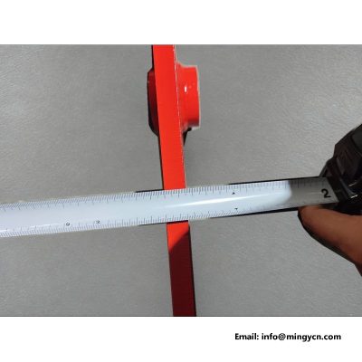
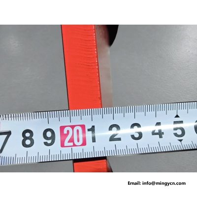
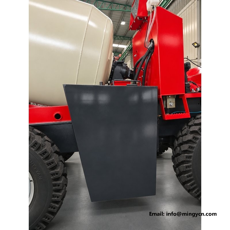
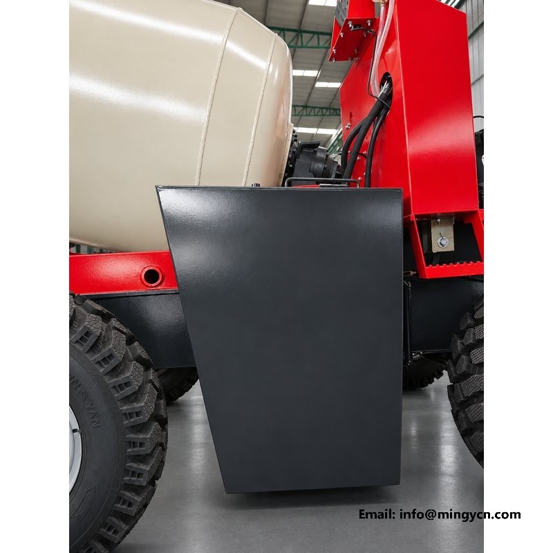
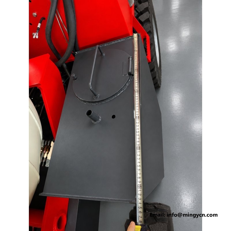
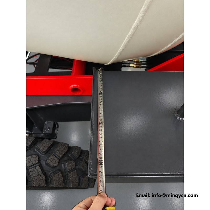
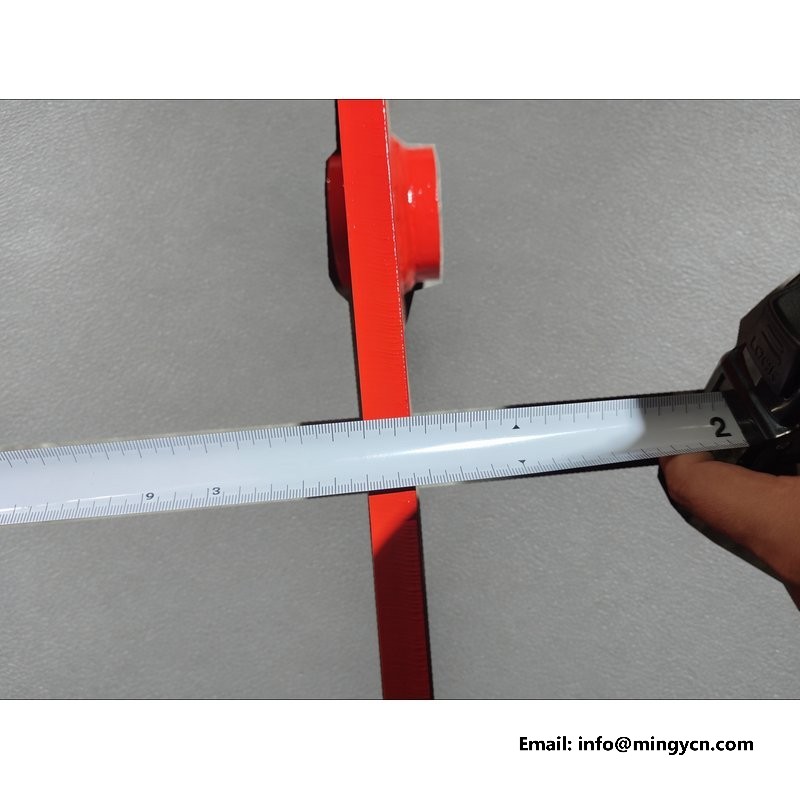
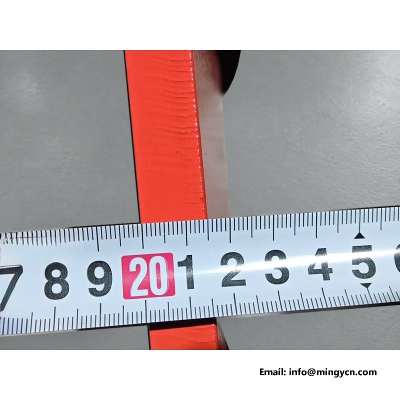
The photographs on this page were taken with a tape measure laid against the machine: close views of red steel parts, the water tank and the guard, with the markings and a finger holding the tape in frame, plus a whole-machine view and two views of the tank. They are the closest thing to a dimension check a remote buyer gets before shipping. The notes below turn the specification figures into site decisions: what overall length, width and height mean for a gate or a trailer, how the turning circle and ground clearance shape the ground you need, how operating weight and rated load differ, how to repeat the measurements with a tape, and why the turning circle and gear descriptions belong in the technical file.
The published figure of 3,500 by 1,600 by 2,200 mm is length by width by height, and it is the first thing to translate into the space you actually have. Length decides whether the machine fits on a trailer or in a storage bay with the shovel folded; width decides whether it passes a gate; height decides whether it clears a shed roof. Measure the site, not the catalogue: a gate opening is usually narrower than the gap between its posts once hinges and a latch are counted. Allow room for the driver to walk round the machine and for the drum to discharge, since the footprint of the parked mixer is smaller than the footprint of the working one. Note the figures as a set, because changing one rarely changes the others, and a plan drawn from only the length is a plan that will be corrected on delivery day.
The 2,200 mm overall height is the dimension that most often decides whether a delivery succeeds. Check it against every opening on the route: the workshop door, a low shed beam, an overhead cable, a tree branch on the track in, and the headroom under a bridge or a canopy. The published figure is static, measured on level ground, so allow for the machine rising and dipping as it crosses a threshold or a ramp, and for any fixture mounted above the guard. On rural sites the obstruction is rarely the doorway itself but something just beyond it. If the clearance is close, plan a different approach or remove the guard for the move rather than discovering the limit with the machine already on the truck. A tape held at the opening is cheaper than a bent frame and a returned load.
At 1,600 mm wide the mixer is narrow enough for many village tracks, but that figure is the machine, not the road. Measure the clear width between walls, hedges, parked vehicles or vineyard rows, and remember that the outer tyre edges, the mirrors and any projecting bracket set the real envelope. On a single-track lane the question is not just whether the machine fits but whether anything can pass it, and where the nearest widening is if it cannot. Site gates are the common trap: the posts are often closer than the gate leaves suggest, and a driver turning in at an angle needs more than the straight width. Walk the approach with a tape before the first delivery, and mark the pinch points so every driver uses the same line rather than finding their own.
The 2,464 mm turning circle and the 28 degree steering angle describe the same behaviour from two sides: the angle is how far the steered wheels turn, and the circle is the swept path that results at full lock. For a 3,500 mm long body, the practical point is that the rear of the machine overhangs outside that circle, so a turning pad has to be clear for the body as well as for the outer tyre edge. On a confined yard this is what lets the mixer turn between a stockpile and a foundation without a long reversing run. Both figures come from the supplied data sheet. Use the pair together when you sketch a site layout, and treat the circle as a minimum clear area rather than a comfortable one, leaving working room around it for the shovel and for a person on foot.
The 204 mm minimum ground clearance is most useful when you read it as a ramp and breakover limit. A loading ramp changes angle at its top edge, and a machine with a long wheelbase can put its frame down on that crest even though each axle clears it on the flat; the steeper the ramp and the sharper the transition, the more of that margin is used. The same applies to a ridge between wheel ruts or a kerb at a site entrance. Keep the approach gradual, build up a shallow ramp rather than a short steep one, and check the underside after the first load for scrape marks. With a full drum the machine sits lower than the static figure, so the margin is smaller exactly when the load is largest and a scrape is most likely to be missed.
The 1,900 kg operating weight is the machine itself, and it is the figure to give the person supplying a trailer, a ramp or a loading platform. It is not the same as the 5,000 kg rated load, and confusing the two is the most common mistake in a transport plan: the trailer and its ramps have to carry the machine plus whatever is left in the drum and tank, while the rated load describes what the mixer is built to work with. Check the ramp rating, the tie-down points and the deck length against the 3,500 mm body, and make sure the trailer brakes and the towing vehicle are matched to the loaded combination. Weigh the machine if the transport margin is tight rather than relying on a rounded figure, and keep that reading with the handover papers.
Three figures on the table are easy to mix up: the 1,900 kg operating weight, the 5,000 kg rated load and the 1.5 m3, or 1,500 L, nominal drum capacity. The rated load is a limit on what the machine is built to carry, and the drum capacity is the volume of one batch. Plan a pour by the number of batches the drum can turn, then check that the materials and water for a full batch stay within the rated load, because volume and weight are different constraints. Do not treat either figure as a target to fill on every cycle; a machine worked at its limit on rough ground has less margin for braking and steering. Keep the three numbers separate in every quotation and site calculation, and state which one each figure refers to.
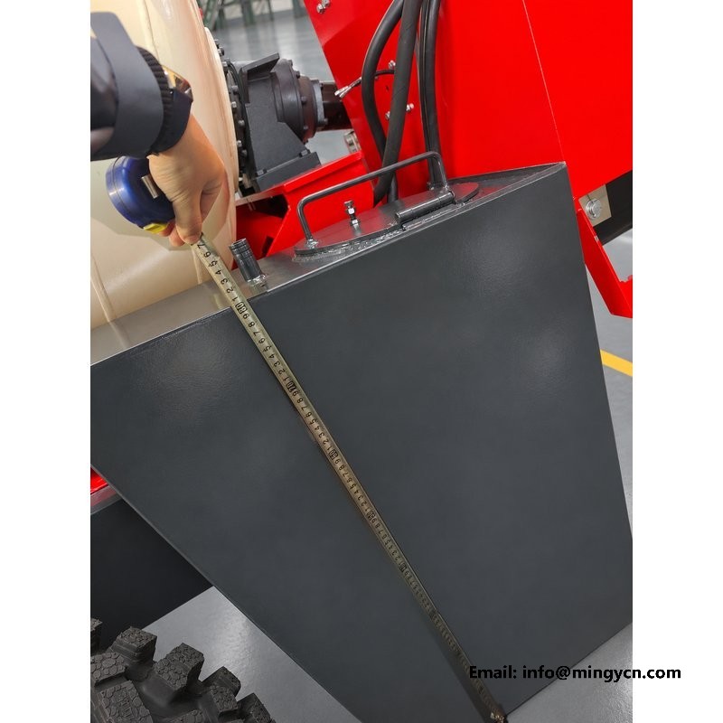
The tape-measure photographs show a method a buyer can repeat, and repeating it is worth doing at handover. Park the machine on level, firm ground with the shovel lowered and the drum empty, then measure length from the frontmost fixed point to the rearmost, width across the outer tyre edges, and height from the ground to the highest fixed point. Keep the tape straight and square to the surface, hook the end on a real edge rather than holding it in the air, and read the markings at eye level to avoid parallax. Take each measurement twice, from opposite sides where you can, and write the readings down against the data sheet. A tape that sags or is read at an angle will give a figure that disagrees with the table for the wrong reason, and a disagreement is worth chasing before it becomes a transport problem.
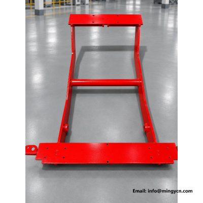
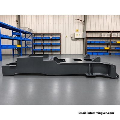
The close-up photographs are useful as evidence of how the measurements were taken, not just what they say. Look for the tape lying flat against the red steel with the graduations clearly in frame and a finger holding the end, which tells you the reading was taken against a real edge and not estimated across a gap. Check that the tape runs parallel to the member being measured, and that the hook or the zero mark is actually at the start of the surface, since a reading taken from the wrong end is a common source of a mismatched figure. Where the tape crosses a weld or a bracket, note it. Use the whole view of the assembled machine to confirm which part each close-up belongs to, then compare the recorded values with the specification table.
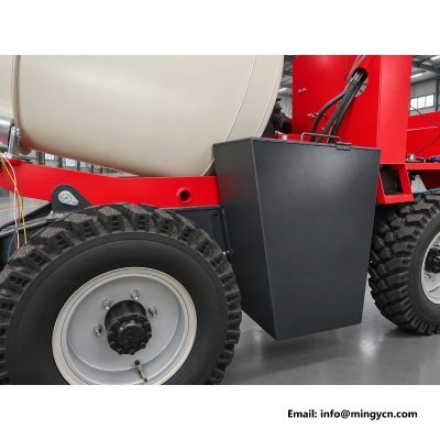
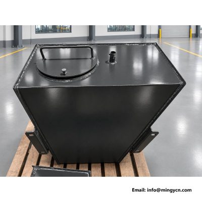
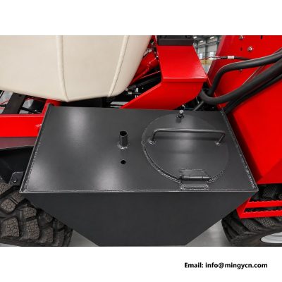
The two water tank views belong in a dimension check because the tank is one of the parts that sets the real width and height of the machine. In the side photographs it sits behind the operator station, strapped to the frame, and its filler, straps and any projecting pipe can extend beyond the tidy rectangle of the chassis. Check the tank mounts and straps for a secure, square fit, look at the filler and cap for a clean seal, and confirm that nothing on the tank pushes the machine past the stated 1,600 mm width. A tank that is loose or sits proud of the frame changes both the measurement and the balance as a batch is mixed. Photograph the mounting from the same angle as the tape views so the two can be compared at handover.
A specification table is only as good as the definitions behind it, so read the notes as part of the numbers. Figures such as the 2,464 mm turning circle are tied to a stated measurement point, here the outer tyre edge, and the gear description of three forward and one reverse plus road gear is a description of ranges rather than a count of road speeds. Units matter too: millimetres for dimensions, kilograms for weight and load, degrees for the steering angle, and kilometres per hour for the 24 km/h maximum travel speed. Turning circle and gear description follow the supplied data sheet, so do not reinterpret them from a photograph. Record which document each figure came from, because a tender or a site plan will be checked against it later and a loose definition is hard to defend.
The last step before quoting any of these figures is to confirm them against the technical file. The turning circle and the gear description on the table follow the supplied data sheet, and their final definitions should be checked there rather than inferred from the photographs or from a similar machine. That is worth doing even for figures that look straightforward, because a turning radius measured at a different point or a gear range counted differently changes a site layout or a transport plan. Ask the supplier to state the measurement basis in writing, keep that note with the handover documents, and use the same source for the 28 degree steering angle and the 204 mm ground clearance. A consistent set of definitions is what makes the rest of the table usable rather than merely printed.
| 1.5 m³ self loading concrete mixer — tape-measured dimensions, turning circle, transport envelope | |
|---|---|
| Model | 1.5 m³ 4WD self loading concrete mixer |
| Rated load | 5,000 kg |
| Nominal drum capacity | 1.5 m³ (1,500 L) |
| Operating weight | 1,900 kg |
| Overall dimensions (L x W x H) | 3,500 x 1,600 x 2,200 mm |
| Front / rear tyres | 750-16 / 750-16 |
| Minimum ground clearance | 204 mm |
| Steering angle | 28° |
| Turning circle (outer tyre edge) | 2,464 mm |
| Gearbox | 4WD, three forward and one reverse plus road gear |
| Maximum travel speed | 24 km/h |
| Front axle | Isuzu-type reinforced front axle |
| Rear axle | 130 four-wheel steering axle |
| Engine | Single-cylinder diesel, 25 hp |
| Steering | Hydraulic power steering |
Turning circle and gearbox descriptions follow the supplied data sheet; final definitions should be confirmed in the technical file before order.
Judge it against the stated 2,200 mm overall height and 1,600 mm width, and measure the clear opening rather than the door frame. Allow for the ground being uneven and for the machine moving on its suspension as it crosses a threshold, because the published height is a static figure. Low branches, cables and roof beams are the usual surprises on rural sites. If the opening is close to the figure, arrange a different entry before the delivery truck arrives.
It is the circle swept by the outer tyre edge at full lock, so it describes the space the machine needs to turn, not the path of its centre line. Plan a clear pad that accounts for the outer edge plus the 3,500 mm body length overhanging behind it. The figure and the three forward and one reverse plus road gear description both follow the supplied data sheet, so confirm their final definitions in the technical file before you quote them in a site layout.
No. The 1,900 kg operating weight is the machine itself, while the 5,000 kg rated load is the payload it is built to carry and the 1.5 m3, or 1,500 L, is the nominal drum capacity per batch. Keep the three figures separate when you choose a trailer, a ramp or a working platform, and when you work out how many batches a pour needs. The rated load is a limit, not a target to fill on every trip.
For the current 1.5 m³ self loading concrete mixer specification, engine options and a formal quotation for your market, contact MINGYI Machinery. E-mail: sales@mingycn.com | LINE (ID): mingyicn
Mini Self Loading Mixer, Compact by Design: 1,600 mm Wide · Tunnel Self Loading Concrete Truck: 2,200 mm · Low Clearance 0.8m3 Mixer: Working Under 2,200 mm · Mini 0.8m3 Self Loading Truck: The Short Envelope
More in the 1.5 m³ series: 1.5 m3 Self Loading Concrete Mixer: Full Specification and Walkaround · 1.5m3 Self Loading Mixer Water Tank: Filler, Capacity and Mounting · Water Tank Fabrication on the 1.5m3 Mixer: Welds and Baffles