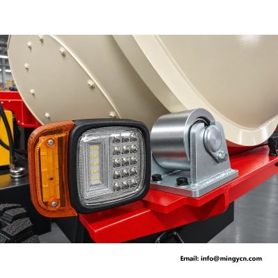
Reversing Camera, Cab Monitor and LED Work Lights on the 1.5 m3 4WD Self Loading Concrete Mixer for One-Operator Site Work
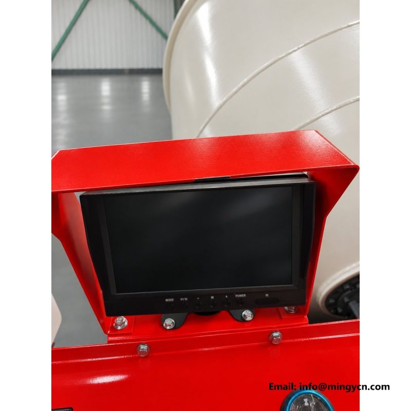
A self loading mixer is a one-person machine, which is why the reversing camera and its monitor matter more here than on a crewed site. The operator loads, mixes, discharges and repositions alone, often with the drum and the loading shovel blocking the view behind. This page looks at the display in its red housing, the row of buttons beneath the screen, the rear camera with its ring of LED fill lights, and the LED work and indicator lamp assembly. It covers where the camera is mounted, how to keep the lens clear, what the buttons do, how the cabling is routed, and how to work through a blank or flickering image. The photographs are treated as evidence of build quality, not a parts list.
One person runs the whole cycle on this machine, from shovelling aggregate to placing the mix, so there is no banksman standing behind to wave the driver back. The cab faces forward, the drum sits high and the shovel frame occupies the front, which leaves a substantial blind area directly behind the rear axle. A monitor fed by a rear camera closes that gap for the repositioning moves that happen between pours. It does not replace a walk around the machine before the first reverse of a shift, but it removes the guesswork from the small corrections that follow. For a buyer, the value is not the presence of a screen; it is whether the view is clear, stable and positioned where the operator can glance at it without leaving the controls. That is the standard to apply to the photographs on this page, and to the handover check before the machine leaves the yard.
Village lanes, farm tracks and partly built foundations leave little room to reposition a loaded machine, and the geometry of this chassis makes precision possible rather than optional. A steering angle of 28 degrees and a turning circle at the outer tyre edge of 2,464 mm let the mixer work in confined yards, while 204 mm of ground clearance helps it cross rough approaches without bellying out. Those same tight dimensions mean a small error in reverse puts a wheel into a drain or a corner into a stack of materials. Hydraulic power steering keeps the correction light, but the driver still needs an accurate view of what is behind the rear tyres. Those figures come from the supplied data sheet, so treat the technical file as the authority before setting them down as certified site limits. A clear rear image turns that tight geometry into an advantage instead of a hazard.
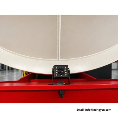
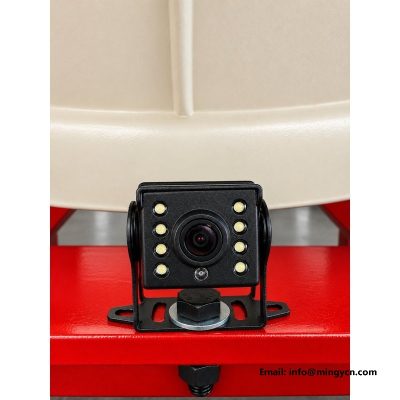
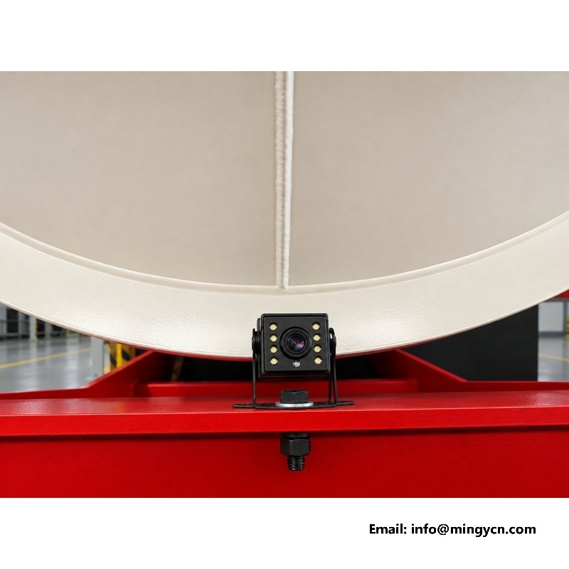
The camera is a compact black unit mounted high at the rear, with a ring of LED fill lights around the lens. Height matters: a low position is quickly coated in slurry thrown by the drum and the chute, while a camera set too high loses the near ground where a person or a kerb is most likely to appear. The bracket should hold the unit clear of the discharge path and away from the shovel's swing, and it needs enough stiffness that the picture does not dance when the single-cylinder diesel 25 hp engine is idling. Ask whether the mount is welded to the frame or bolted through a reinforced plate, because a vibrating image is tiring to use and usually traces back to a flimsy bracket rather than the camera itself. Check that the lens points slightly downward so the view includes the rear tyres and the ground between them.
Cement slurry, dust and rain all find the lens, and a coated camera gives a picture that looks like fog long before it fails outright. Wipe the glass and the LED ring with a soft cloth at the start of each shift and again after any discharge that threw material toward the rear. Avoid abrasive pads, since a scratched lens scatters the LED light and flattens contrast at night. When washing the machine, keep a high-pressure jet off the lens seal and the cable gland; water driven into the housing shows up later as condensation inside the glass. A thin film of dried mortar on the LED ring cuts the fill light just as effectively as dirt on the lens, so clean both together. This is a small habit, but it decides whether the system is usable on a dusty afternoon, and it takes less effort than diagnosing a supposedly faulty camera afterwards.
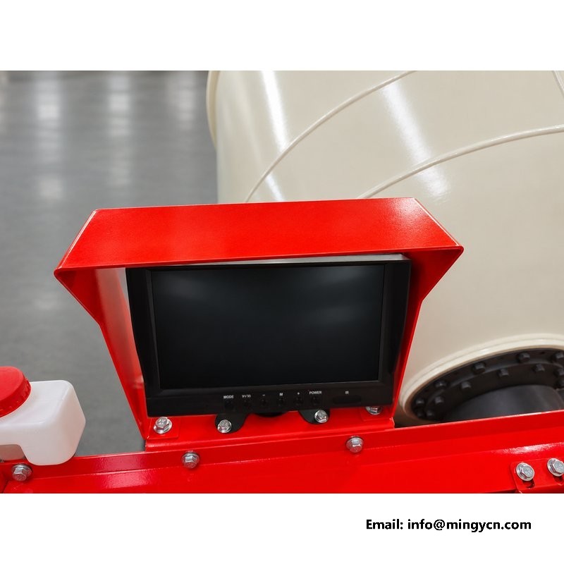
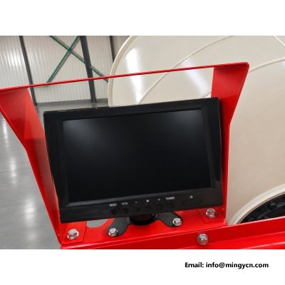
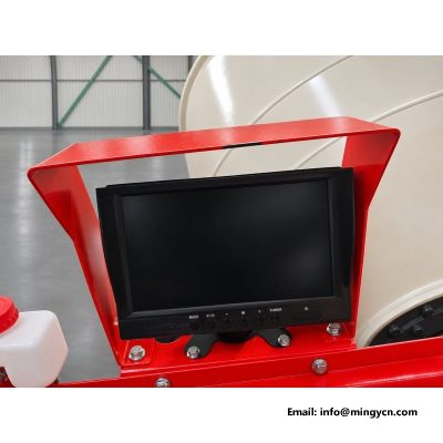
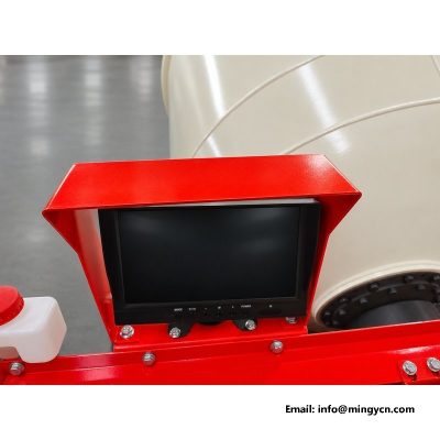
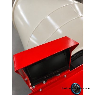
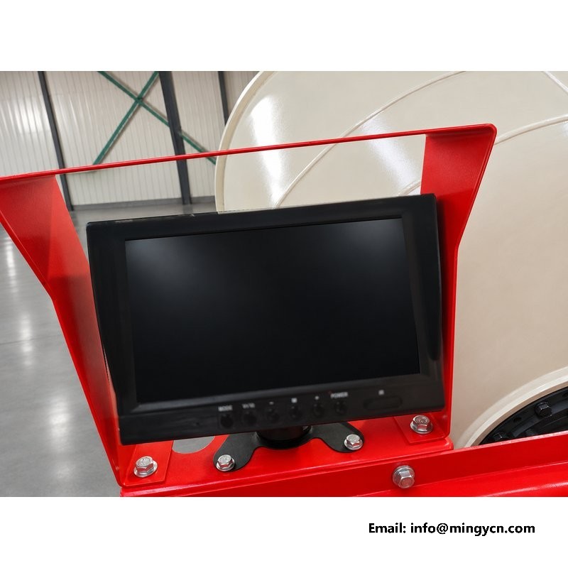
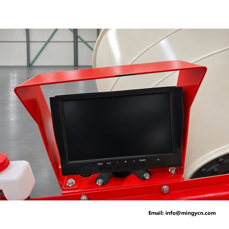
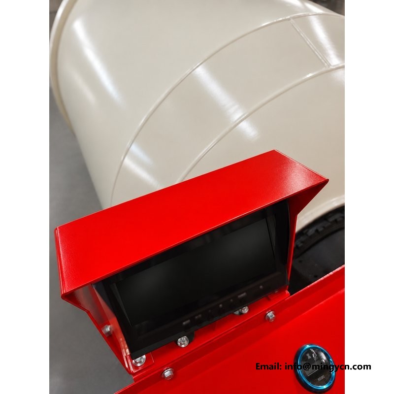
The monitor sits inside a red housing with a row of physical buttons directly below the screen. Physical controls are deliberate: an operator wearing work gloves, with wet or dusty hands, cannot reliably use a touch surface, and a raised button can be found without looking away from the reversing path. The row typically handles power, brightness and contrast, input or view selection, mirror reversal and the on-screen menu, so confirm the exact mapping in the handover documentation rather than assuming a layout. Check that the labels remain legible after cleaning and that each button has a positive, sealed feel instead of a soft membrane that traps grit. Photographs taken from several angles are useful here, because they show the spacing of the buttons and whether the housing gives the screen a shading lip against low sun. Press every control during the pre-shift check, not just the power switch.
The red enclosure is more than a colour choice; it is the first line of defence for the screen and its electronics on an open machine. Look for a continuous gasket where the front bezel meets the case, button openings sealed behind a membrane rather than left as through-holes, and cable entries that point downward so rain runs off instead of tracking inward. Machines that work uncovered need the housing to shed water from above and resist the fine cement dust that works into every seam. Condensation is the quiet failure mode: a screen that clears as the cab warms up has moisture inside, usually from a damaged seal or a poorly seated connector. Ask how the unit is rated for washdown, and treat any sign of a gap at the bezel as a reason to request a replacement before the machine leaves the yard. A sound enclosure also keeps vibration from loosening the display on its mount.
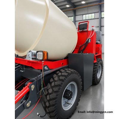
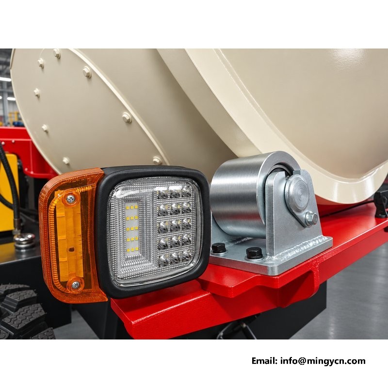
The ring of LEDs around the camera lens is a fill light for the sensor, not a floodlight for the site, and understanding that difference prevents disappointment on an evening pour. It lifts the area immediately behind the machine enough to separate a person from a shadow, but it will not illuminate a long reverse path or replace the separate LED work and indicator lamp assembly shown in the photographs. That assembly, which combines a work light with the turn indicator, lights the working area and signals the machine's movement to anyone nearby. At night, set the monitor brightness so the LED ring does not bloom into a white patch that hides detail, and check that the camera is not pointed at a reflective surface. Confirm the lamp wiring is protected where it passes near the drum and the rear frame, since a chafed feed here fails at the moment it is most needed.
Most faults that look like a failed camera turn out to be a connector or a chafed cable. Trace the loom from the rear bracket along the frame, and check that it is clipped clear of the lift arms, the drum saddle and any hot surface near the engine bay. Vibration from the single-cylinder diesel 25 hp unit is constant, so a cable left to rub on a plate edge will eventually short or open. Connectors should be the sealed type, seated fully, with any excess loop tied so it cannot snag during washing. Confirm the power feed is fused and that the ground returns to clean metal rather than a painted bracket. When reviewing a new machine, ask for the routing to be shown in photographs, because wiring hidden behind a fitted drum is hard to inspect later and expensive to reach. Insist on a wiring diagram in the handover pack.
Work from the simple end first. A fully blank screen with no button response is usually power, so check the fuse, the supply connector and the ground before condemning the display. A picture that flickers when the engine revs points to a loose plug, a chafed cable or a weak connection rather than the camera itself, especially on a machine with constant diesel vibration. Snow or a grainy image suggests a damaged cable run or water in a connector; a milky white picture at night usually means a dirty lens or an LED ring coated in slurry. If the view is left-right reversed, change the mirror setting in the menu instead of moving the camera. Only after these checks should the display or camera be swapped, and the fault should be logged so a recurring wiring issue is not masked by repeated part replacement.
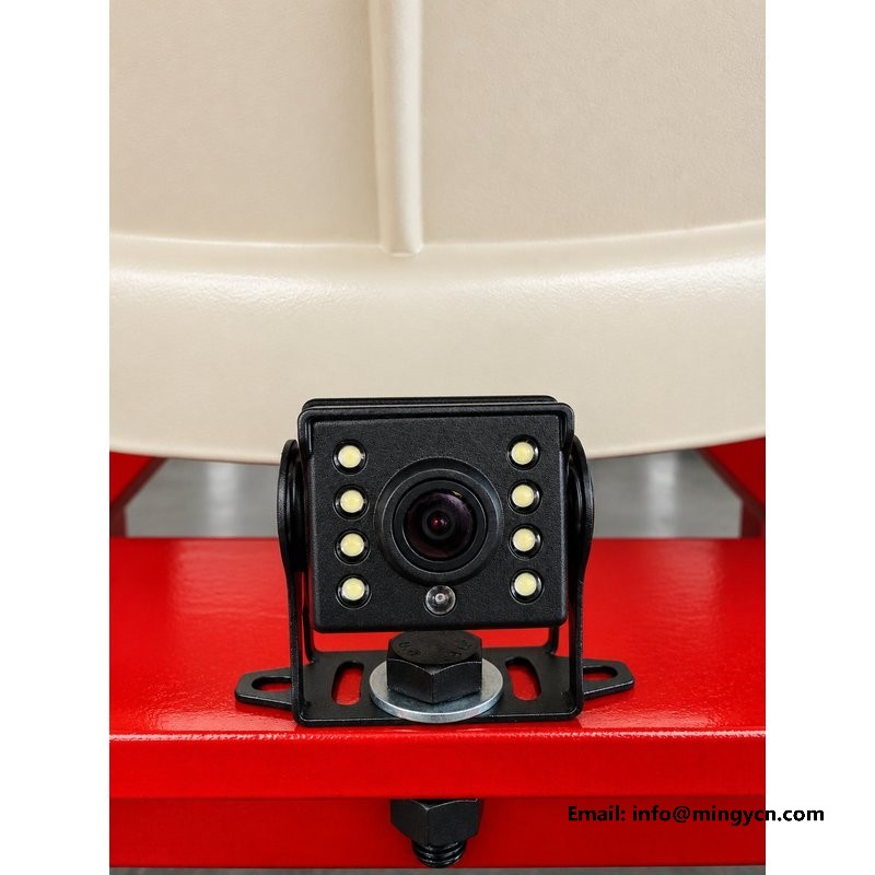
The five monitor images are shot from different angles, which is exactly what a buyer needs to judge the housing rather than just see a screen. Study the seam around the red case, the shading lip above the display, and the spacing and labelling of the button row along the lower edge. The two camera photographs show the black square body, the ring of LED fill lights, and the bracket that fixes it to the rear frame, so look for a rigid mount and a lens that sits proud of its surround. The remaining photograph of the LED work and indicator lamp assembly shows the lens, the mounting ears and how the unit is protected from slurry. Read together, the set lets you assess fit and sealing before the machine is delivered, when corrections are still straightforward and do not involve dismantling an assembled unit.
A short setup at the start of the shift turns the camera from a fitted accessory into a tool the operator trusts. Power the monitor, confirm a stable image with the engine idling, and adjust the camera angle so the rear tyres and the ground immediately behind them are both in frame. Clean the lens and the LED ring, then press each button in the row to confirm it responds and that the brightness suits the light on site. If the machine will work after dusk, check the fill light and the work lamp while it is still easy to correct a problem. Walk around the machine before the first reverse of the day, because a camera shows a fixed sector and cannot reveal a person who has just stepped into the blind area. Record anything that needs attention on the handover sheet rather than carrying it unresolved into the next shift.
Washdown and cold storage are where a camera system is quietly damaged. Keep high-pressure water away from the lens seal, the button membrane and every cable gland, and dry the connectors if the machine is put away wet. In cold conditions, moisture inside a housing can freeze or fog the glass, so a unit that misted during the day should be opened, dried and its gasket checked rather than simply left to clear. If the machine will stand idle for a long period, isolate the supply so the display is not left drawing current, and protect the bracket from corrosion at its fixings. Keep a spare sealed connector and the handover wiring diagram with the service kit. These steps cost little, and they prevent the slow faults that are otherwise blamed on the camera months later, long after the real cause has been forgotten.
| 1.5 m³ self loading concrete mixer — backup camera, monitor, visibility, work lights, single oper | |
|---|---|
| Model | 1.5 m³ 4WD self loading concrete mixer |
| Overall dimensions (L x W x H) | 3,500 x 1,600 x 2,200 mm |
| Gearbox | 4WD, three forward and one reverse plus road gear |
| Steering | Hydraulic power steering |
Turning circle and gearbox descriptions follow the supplied data sheet; final definitions should be confirmed in the technical file before order.
No. The camera covers a fixed sector behind the machine and is meant for small corrections. It cannot show someone who steps into the blind area after the operator has looked at the screen, and it cannot judge distance to a drain or a soft verge as reliably as a person standing there. Walk around the machine before the first reverse of a shift, then use the monitor to stay oriented between pours. Treat the two as complementary, with the camera reducing risk rather than removing it.
Start with the supply and the connectors, not the display. A loose plug, a chafed cable rubbing on the frame, or a ground taken through painted metal will all produce a picture that breaks up when the engine vibrates or revs. Water in a sealed connector gives a similar symptom and often worsens after washing. Check the fuse, reseat each connector, inspect the loom where it passes the lift arms, and only then consider swapping the camera or the screen.
It is a fill light for the camera sensor, intended to lift the ground immediately behind the machine so the picture stays readable in low light. It is not a work light and will not illuminate a long reversing path or a pour site. The separate LED work and indicator lamp assembly shown in the photographs handles area lighting and signals the machine's movement. If the ring is coated in slurry, night images turn milky, so clean the lens and the ring together during the end-of-shift washdown.
For the current 1.5 m³ self loading concrete mixer specification, engine options and a formal quotation for your market, contact MINGYI Machinery. E-mail: sales@mingycn.com | LINE (ID): mingyicn
Easy Operation Self Loader: One Operator, Full Cycle · Single Operator 0.8m3 Concrete Mixer: The One-Person Loop · 0.8m3 Self Loading Mixer from Every Angle: A Photographic Reference · Electric Start Diesel Concrete Mixer: Key Start, No Drama
More in the 1.5 m³ series: Welded Chassis Frame on the 1.5m3 Self Loading Mixer · Roll Bar and Operator Guard on the 1.5m3 Self Loading Mixer · 750-16 Tyres and Isuzu Front Axle on the 1.5m3 Mixer