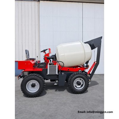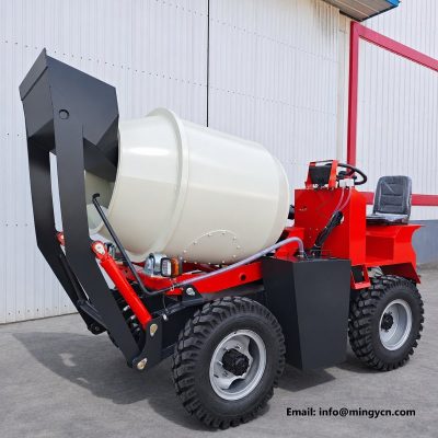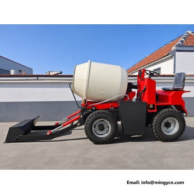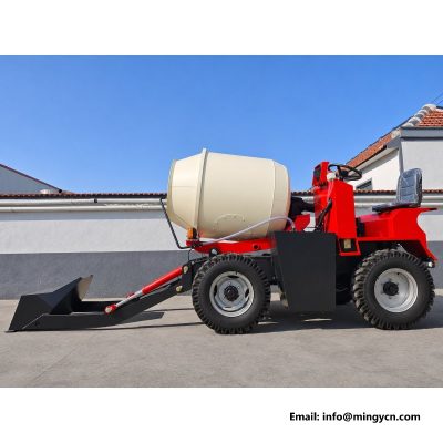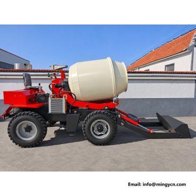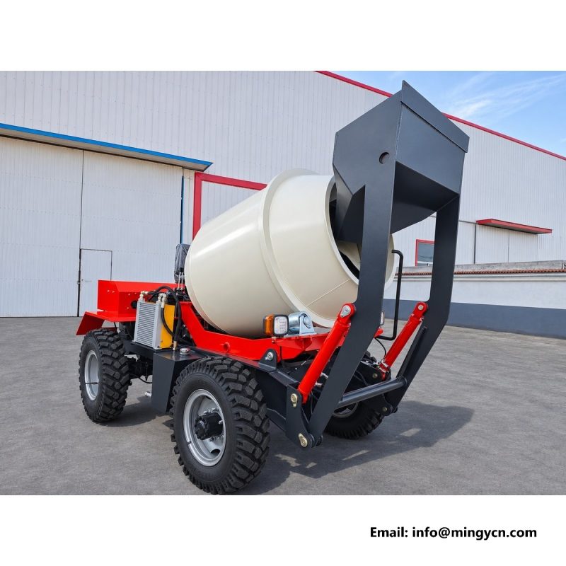
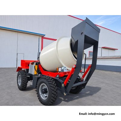
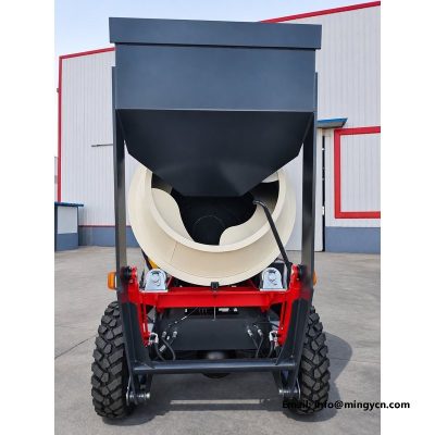
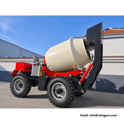
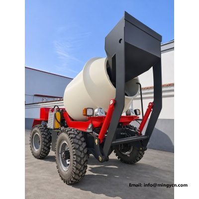
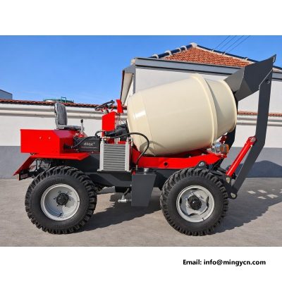
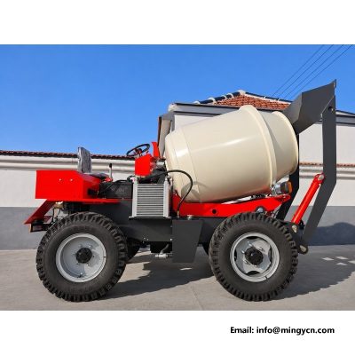
1.5m3 mixer front quarter: hopper, drum and front axle
A set of workshop photographs taken from the front left, at standing height and at ground level, does more for a buying decision than a paragraph of adjectives. This set works around a 1.5 m3 self-loading mixer with a 5,000 kg rated load, and it concentrates on the corner where the hopper, the drum nose and the front axle meet. What follows is a reading order: frame joint first, axle second, tyre and hub third, drum nose fourth, paint last. Each section names the detail to look for, why it matters in service, and what a poor version of it looks like.
| Specification | 1.5 m³ self loading mixer |
|---|---|
| Rated load | 5,000 kg |
| Drum capacity | 1.5 m³ (1,500 L) |
| Overall dimensions (L x W x H) | 3,500 x 1,600 x 2,200 mm |
| Minimum ground clearance | 204 mm |
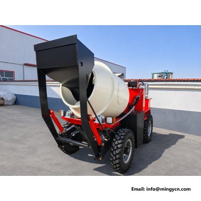
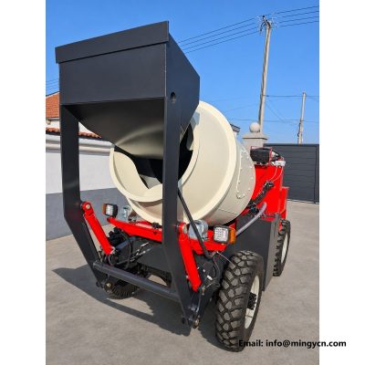
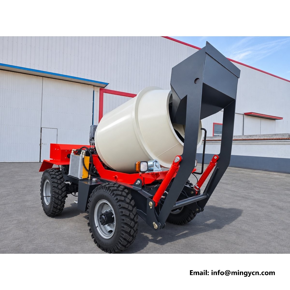
A front quarter view is the first picture most buyers see and the one they examine least. From this angle the machine reads as a silhouette: hopper forward, drum behind, axle underneath. That is good for shape and poor for detail unless the eye is given an order to work in. The angle earns its place because it holds four assemblies in one frame at one scale, so the join between hopper frame and chassis, the axle position, the tyre under the drum and the finish on the drum nose can be compared without walking. Read them in that sequence. Buyers who start with the paint usually stop there, and the three structural questions behind it go unasked until the machine is on site. A level machine in the frame is also a machine whose axle mounts were drilled in line.
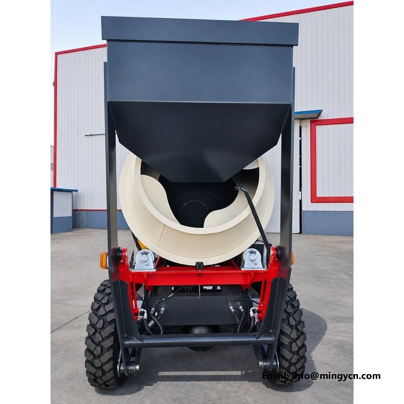
The hopper does not sit on the drum. It sits on a frame that is welded and bolted to the front of the chassis, and that joint decides how the loading shock travels. In the photograph the joint appears as a pair of vertical riser plates rising from the rail ends, with the hopper arms pivoting between them. Look at plate thickness at the top of those risers, and at whether a gusset runs back along the rail. A riser welded only across its base puts the whole reaction on one line. A riser tied back with a triangular gusset spreads it along the rail, and that is what keeps the front end square after a few thousand scoops. That single detail separates a front end that stays square from one that slowly opens at the top of the risers.
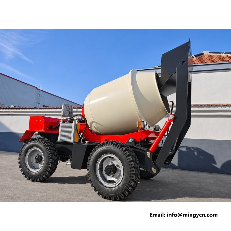
Trace the front axle upward in the picture and you find the drum, not the hopper. That is the logic of the layout: the axle carries the batch, the hopper hangs ahead of it, and the rear axle takes the engine and the steering effort. The reinforced front axle on this machine is specified for that duty rather than borrowed from a lighter application. In the photograph, judge position rather than specification. The axle should sit close behind the forward drum support, so the mass lands between the wheels instead of ahead of them. An axle pushed too far forward shortens the useful wheelbase and puts the front tyres under a lever they were never designed to resist. On a loader this size the axle also carries steering forces, so a beam that looks light at the ends deserves a second look.
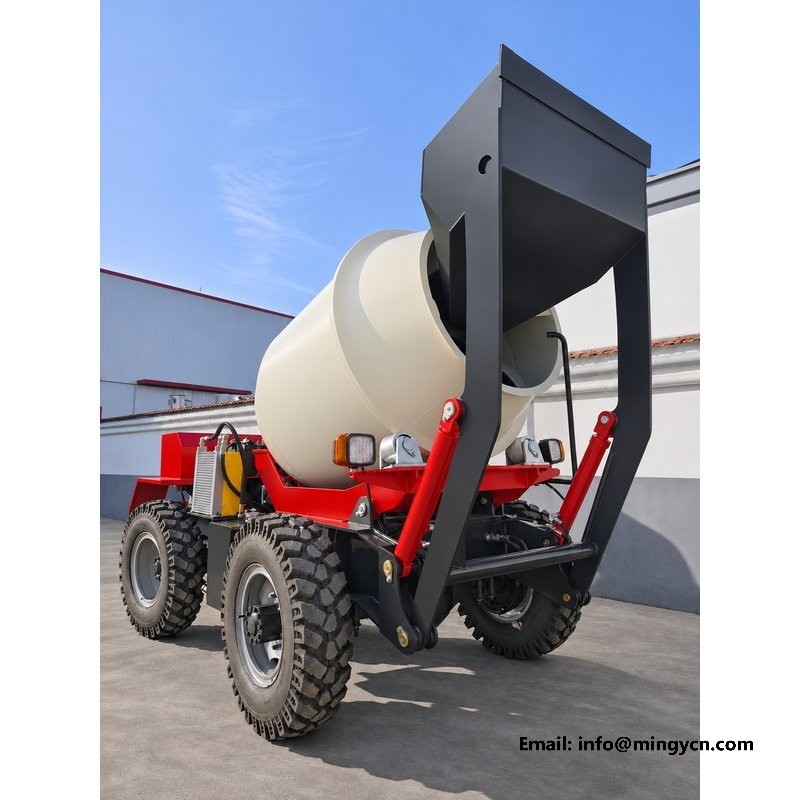
At the front corner the photograph resolves three things at once: the tyre, the rim and the hub. All four wheels on this machine run 750-16, front and rear, which keeps the contact patch and the gearing consistent and means one spare pattern covers the whole machine. Look at how much of the tyre sits outside the body line. A tyre tucked fully under the drum is protected but narrows the track. A tyre standing proud gains stability and collects the occasional gatepost. On the hub, count the visible studs and check that the nuts show thread rather than sitting flush with the rim face. Flush nuts mean the wheel has run loose at some point. A wheel that has been run loose also leaves a bright ring around the stud holes, which no amount of paint hides.
The front of the drum is a cone, and the cone is where a self-loading machine earns or loses its reputation. From the quarter view, the ring that forms the charging opening should sit concentric with the drum axis, with an even gap all round and no deformation at the lip. Deformation there comes from a shovel striking the ring, and once the ring is out of round the opening no longer closes cleanly. Look also at the flange where cone meets shell. A continuous weld with a visible fillet suggests the cone was jigged before welding rather than pulled into place afterwards. The nose is the most abused part of the drum, and the cheapest place to spot a rushed build. Run a hand around the lip on arrival; a ring that has been struck will feel out of round before it looks it.
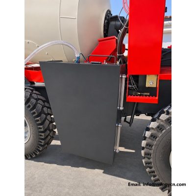
Paint on a construction machine is a preparation report written in colour. Where the finish is thin over a weld toe, the primer went on before the weld was dressed. Where it flakes in a straight line, the edge underneath was sharp. On this front quarter, the drum nose, the hopper arms and the axle beam should all hold the same tone, because they were painted in the same booth at the same stage. A panel that is a shade off has usually been replaced or repainted after damage. Gaps carry information too. An even gap between hopper arm and riser plate says the assembly was aligned. An uneven one says it was forced. On a machine that works in wet ground the lower panels matter most, and that is where thin paint shows first.
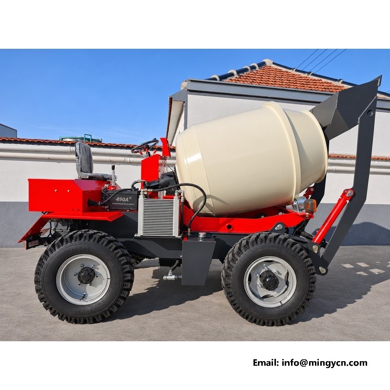
Follow the hydraulic lines from the hopper rams back toward the chassis. Good routing runs them along the frame with clips at regular spacing, crosses no sharp edge without a sleeve, and leaves a service loop at the pivot so the hose flexes along its length rather than at the fitting. Poor routing lets the hose hang, chafe on the arm and fail at the crimp. In the photograph you can see whether the lines are bundled or loose, whether they pass inside or outside the arm, and whether the steering hoses climb clear of the tyre at full lock. With a 28 degree steering angle the front wheels swing wide when parked. Ask for one frame taken at full lock, because that is the position where a badly routed hose shows itself.
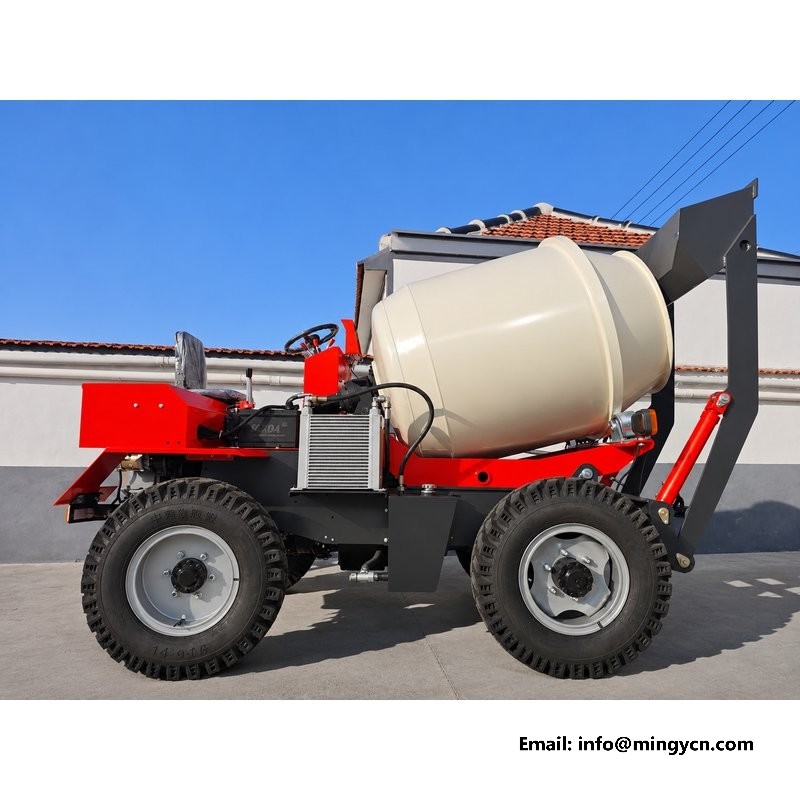
Ground clearance is easy to state and hard to see. At 204 mm the lowest point under this machine sits roughly at the height of a house brick, and a photograph taken from standing height compresses that gap in a way that flatters it. Crouch, or compare the lower edge of the frame against the tyre sidewall, and you get a truer reading. The figure that matters on site is not the clearance under the axle tube but the clearance under the drum saddle and the front crossmember, because those are the parts that meet a rutted track first. Ask which component sits lowest before accepting the number. A machine that measures well on paper and drags its belly on the first track was specified from a desk.
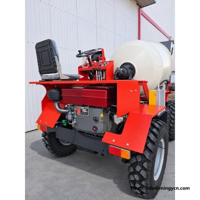
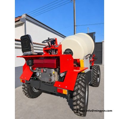
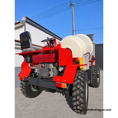
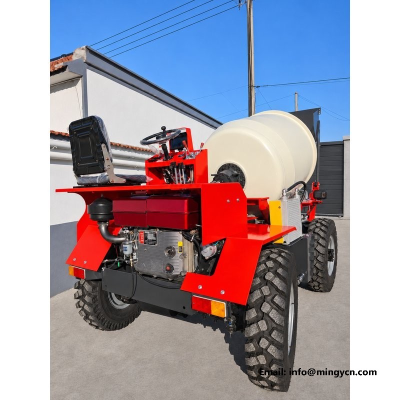
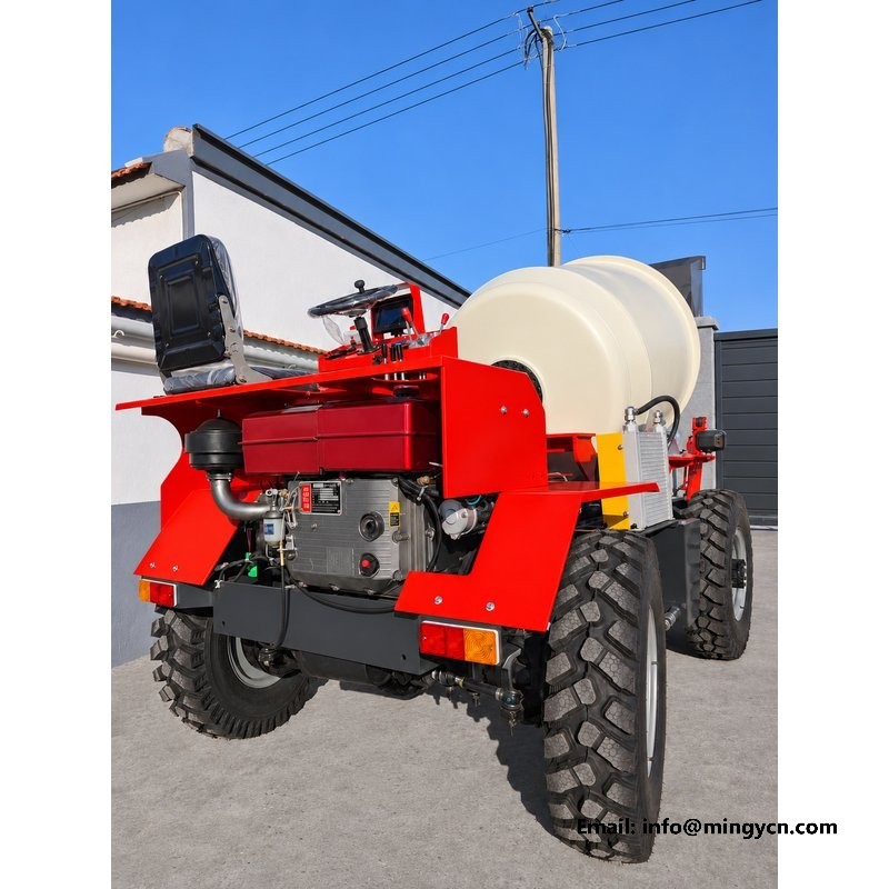
The front quarter is honest about layout and silent about three things: the far side, the underside and the rear. It cannot tell you whether the left frame rail mirrors the right, whether the drum drive is guarded, or whether the rear axle carries its steering linkage cleanly. It also hides the ground under the machine, so a frame taken on a concrete apron says nothing about how the tyres sit on soft ground. When a supplier offers only this view, ask for the opposite corner, a straight side elevation, and one frame taken at ground level from behind. A sound build survives that request without argument. A gallery from four corners costs a supplier an hour and saves a buyer a site visit.
On arrival, walk to the front quarter and repeat the photograph with your eyes. Check that the hopper arms swing without fouling the risers, that the tyre sidewalls face the same way on both sides, and that the drum nose ring is still round after transport. Look for fresh paint on bolt heads, which usually means something was removed and refitted in a hurry. Sight along the lower edge of the axle beam to confirm it is straight, and check that the steering ram is not at the end of its stroke with the wheels pointing ahead. None of this replaces a proper inspection. Photograph what you find, date it and keep it with the delivery paperwork. Keep the file with the machine history, because a delivery photograph is worth more than a memory of one.
Only indirectly. The drum is rated at 1.5 m3, or 1,500 litres, and the cone and shell proportions should look consistent with that volume against the 1,600 mm body width. What the angle confirms reliably is the relationship between drum nose and hopper: whether the charging ring clears the hopper lip, and whether the drum sits far enough back for the front axle to carry it. Ask for a straight side elevation if you need to judge volume rather than layout.
All four wheels run 750-16, which simplifies spares and keeps the rolling circumference matched across the four-wheel-drive system. On a four-wheel-steer machine that matters more than on a two-wheel-steer one, because the rear axle steers as well and any difference in tyre height between axles works the driveline continuously. A single spare pattern also means one tyre on the truck covers every corner, a practical advantage where the nearest dealer is a long drive away.
For the current specification, build options and a formal quotation for your market, contact MINGYI Machinery. E-mail: sales@mingycn.com | LINE (ID): mingyicn
1.5 m3 Self Loading Concrete Mixer: Full Specification and Walkaround · Loading Hopper and Lift Arm on the 1.5m3 Self Loading Mixer · 1.5m3 Self Loading Mixer from Every Angle: A Yard Photo Reference