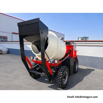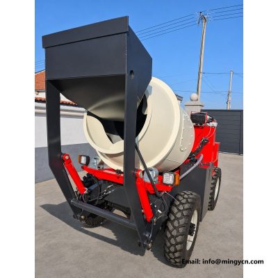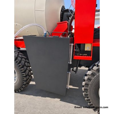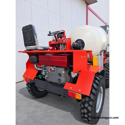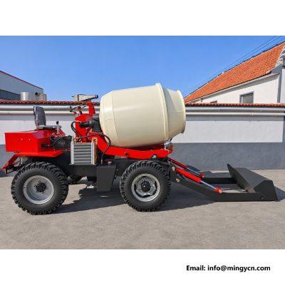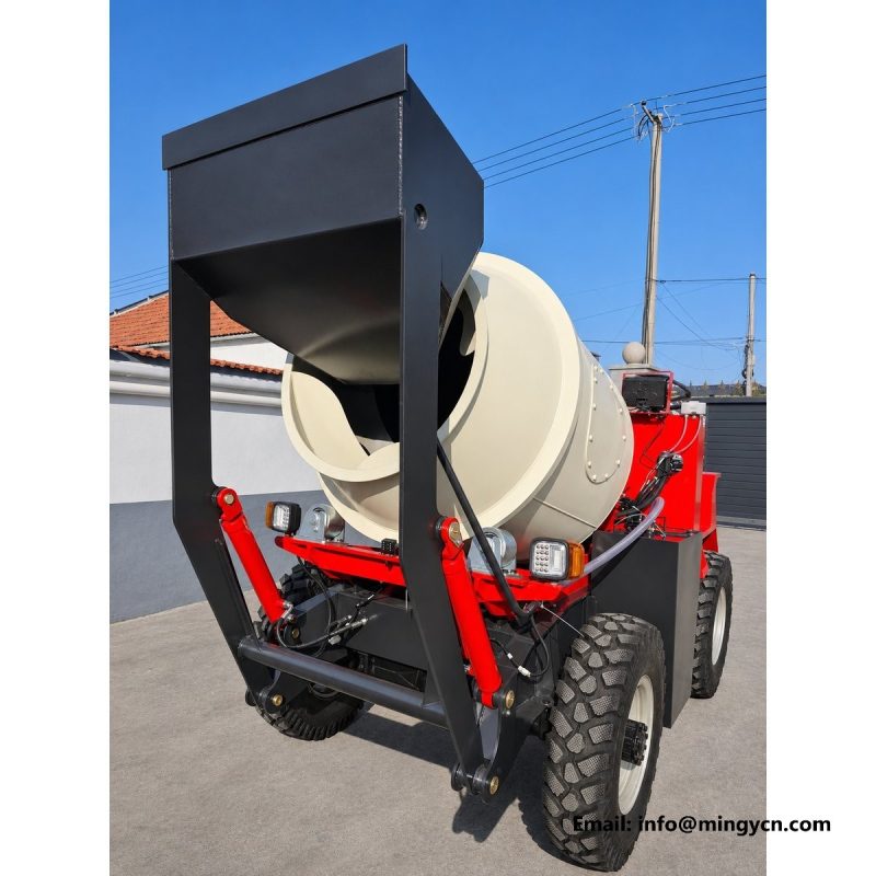
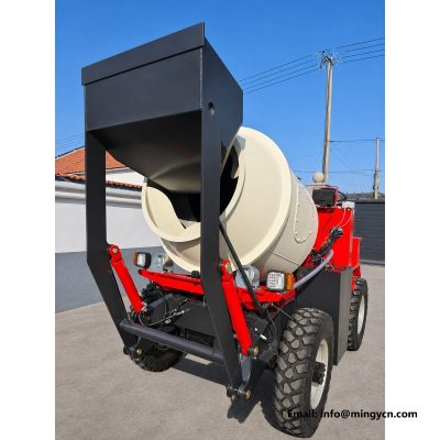
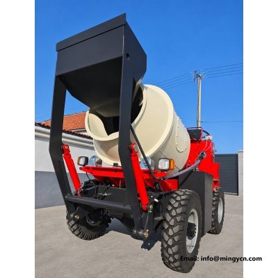
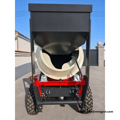
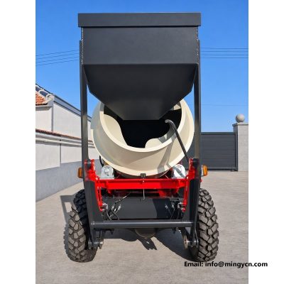
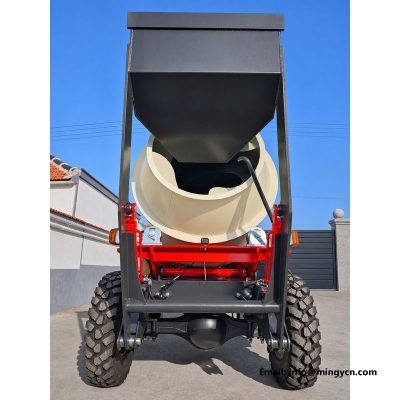
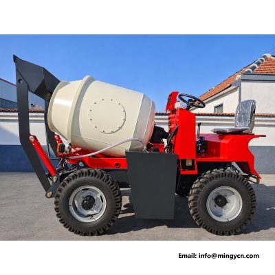
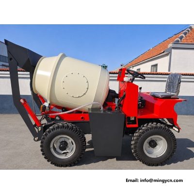
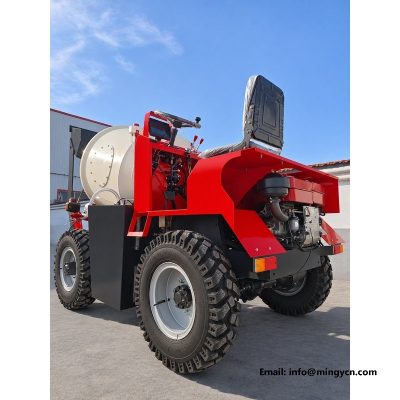
hopper at loading height: bucket geometry from the ground
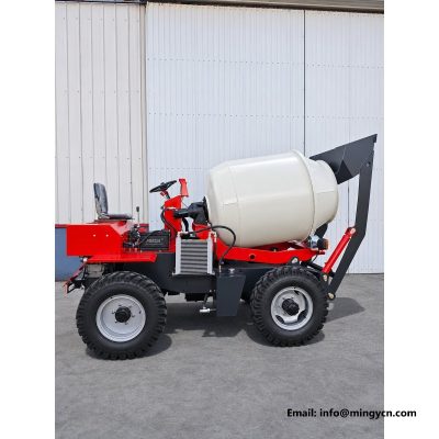
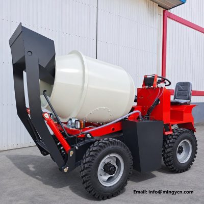
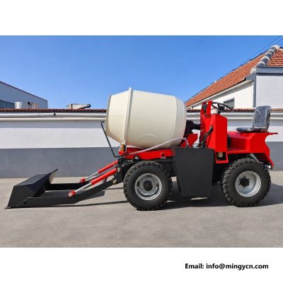
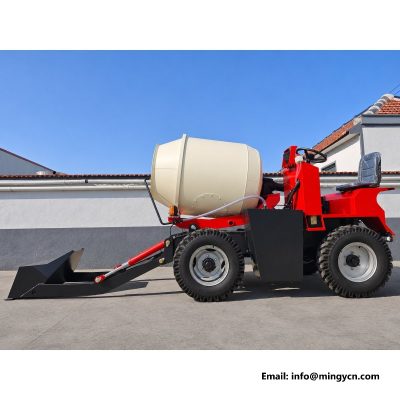
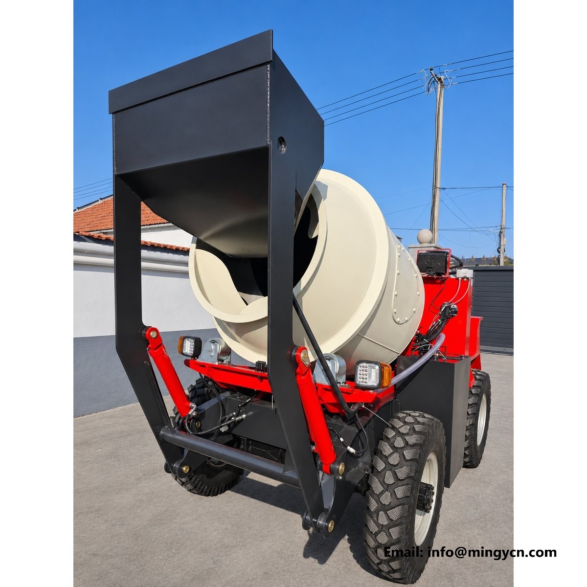
Loading height is the part of a self-loading mixer that no specification table describes. These photographs were taken with the hopper raised and the camera at ground level, which is the only position that shows the mouth as the material sees it: lip line, wall angle, arm angle and the gap to the drum opening in one frame. The machine is the 1.5 m3 build with a 5,000 kg rated load and a 1,900 kg operating weight. The sections below read the raised geometry in the order a driver meets it, from the first cut into a pile to the last of the load leaving the hopper.
| Specification | 1.5 m³ self loading mixer |
|---|---|
| Rated load | 5,000 kg |
| Drum capacity | 1.5 m³ (1,500 L) |
| Overall dimensions (L x W x H) | 3,500 x 1,600 x 2,200 mm |
Almost every studio photograph of a self-loading mixer is taken at chest height, which hides the one thing that decides loading speed: the shape of the hopper mouth as a shovel sees it from a stockpile. A ground level frame at full lift answers a different question. It shows the lip line, the wall angles and the height of the mouth above the ground in one view, and it shows them against the drum mouth rather than against a clean background. That is close to the view a driver has when the arm is up. Frames taken from this height also show the underside of the mouth, which is where a hopper either clears a slope or digs into it.
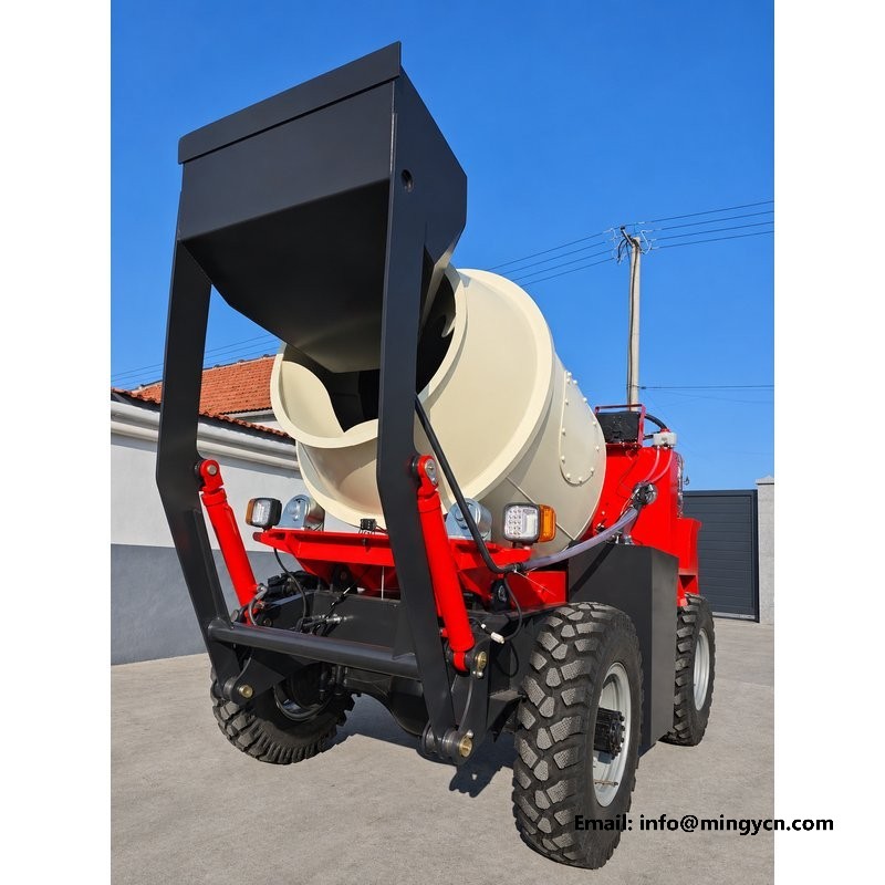
Read the hopper mouth as a rectangle with two jobs. The lip has to cut into a pile, and the corners have to hold the load without spilling it sideways. In the raised photographs the lip should run straight across with a reinforced edge, and the corner plates should appear as separate pieces rather than a single folded sheet. A folded corner is cheaper and cracks at the fold after enough cycles. Check also that the mouth is wider than the drum opening behind it, so a full bucket can be tipped without steering the machine to find the centre. A lip hard faced along its edge suggests the builder expected wear on the cutting line. A mouth beaten back into shape with a hammer shows ripples along the lip, and ripples hold material on the next pass.
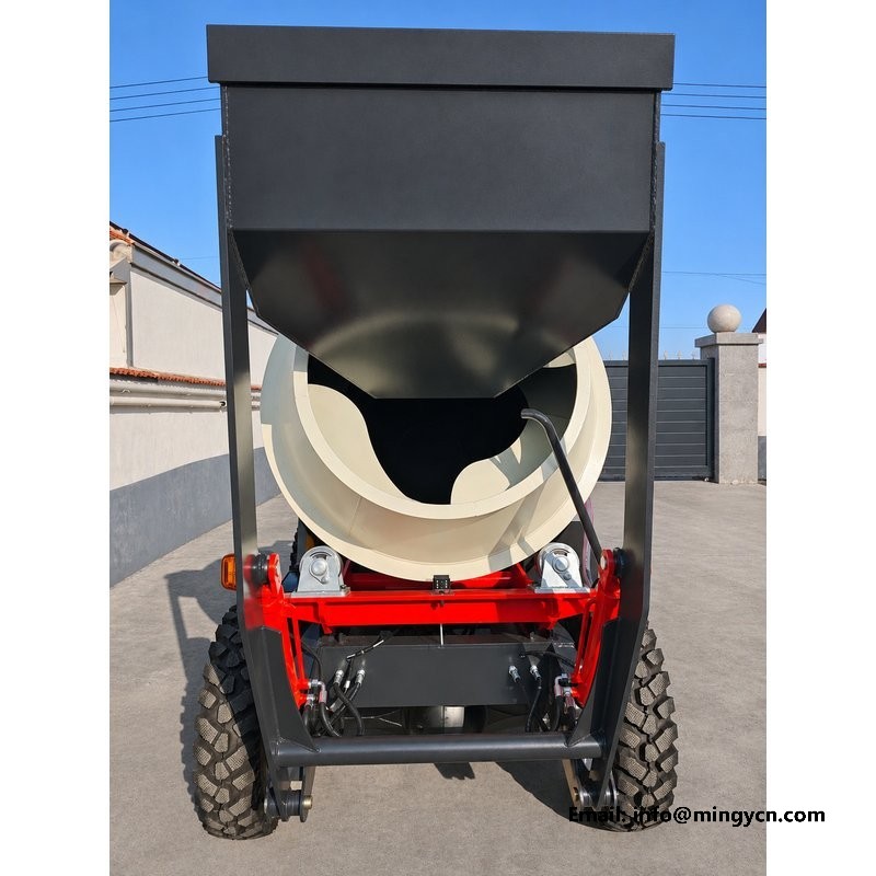
A hopper is a chute that has to empty itself. From the ground, look at the angle of the side walls and the back wall: steep enough that wet sand slides, shallow enough that the mouth stays wide. The back wall is the one to watch, because a load that hangs there has to be shaken out with the hydraulics. In the photograph, the transition between back wall and floor should be a curve or a generous fillet, not a sharp internal corner where material packs. A hopper that empties on the first tip saves a shake of the arms on every cycle. Material clinging to a wall in the frame tells you the surface is rough. Check the floor as well, because a floor that sags between its supports holds a puddle and starts the load sliding late.
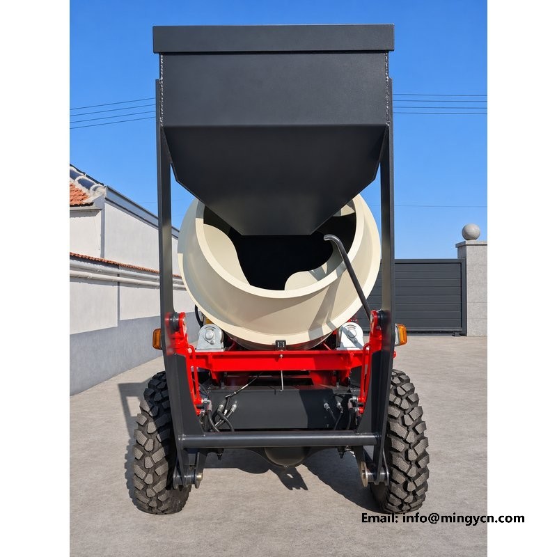
At full lift the arms show how the geometry was laid out. The arm should meet the hopper back at close to a right angle, so the load sits over the pivot rather than hanging off it, and the two arms should be tied by a cross tube that keeps them parallel. In the raised frames look at the arm section. A fabricated box arm resists bending better than an open channel, and the difference shows as a straight arm rather than a bowed one after a season of gravel. Check that each arm clears the drum guard through the whole arc. Both arms should also show the same paint wear at the pivot, or one has been doing more work.
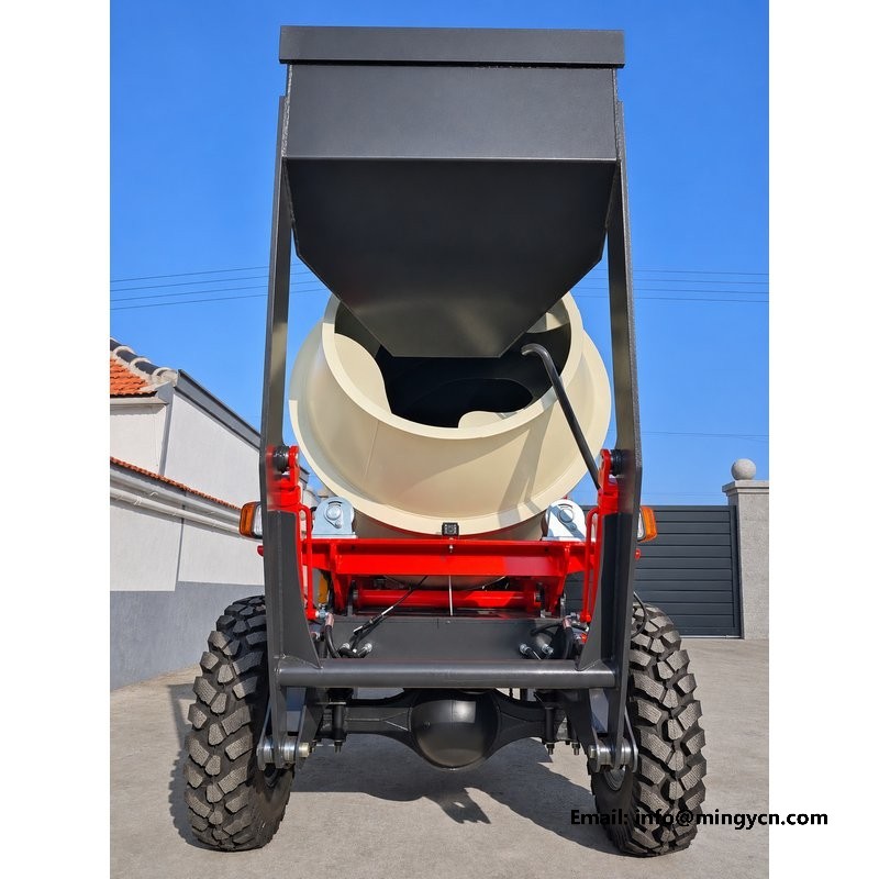
The lift is a triangle: pivot at the chassis, ram from the frame to the arm, load at the mouth. A photograph taken from ground level shows all three sides at once, which is the only way to judge whether the ram works at a sensible angle. A ram mounted too close to the pivot needs high pressure to start the lift. One mounted too far out runs out of stroke before the hopper reaches the drum. Look for the cylinder body protected behind the arm, with the rod end shielded from anything the bucket drags in. A ram with the body forward and the rod rearward is protected on the lift stroke. The pin should be greased from the outside, where a fitting can be reached without lying under the machine.
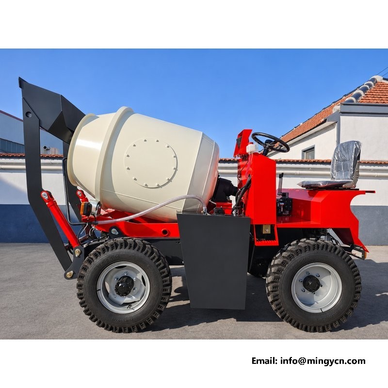
This is the relationship the whole machine is built around. With the hopper at full lift, the lip should sit above the drum opening by enough margin that a tipped load falls in rather than catching the ring, and close enough that the fall does not scatter. The ground level frame makes that vertical gap readable against the drum cone behind it. If the lip sits level with the ring, every bucket has to be tipped slowly. If it sits too high, sand and gravel separate in the air and the coarse aggregate lands first. That same gap decides how much material strikes the drum ring, and a ring struck at every bucket does not stay round. A lip set slightly forward of the ring throws material toward the centre of the drum instead of against the cone face.
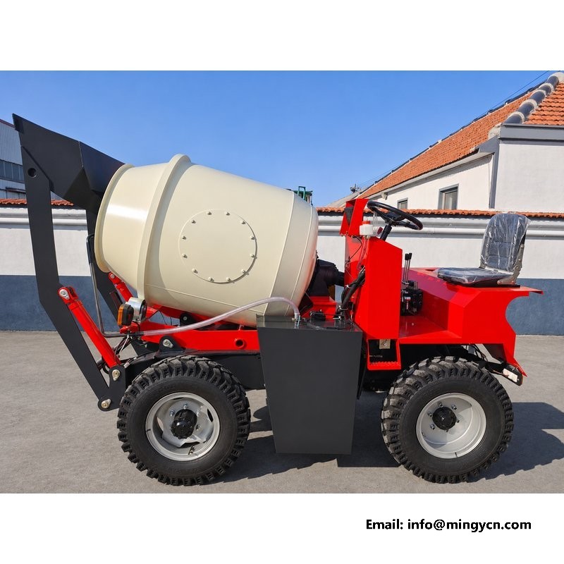
Watch the line from bucket edge to drum opening and you are watching the feed path. It should be short, steep and unobstructed, with no stay, hose or handrail crossing it. In these photographs the path from the raised mouth to the cone appears as a clear opening, and the only thing above it is the arm cross tube. Anything else in that space will collect material or be struck by it. On a windy site the length of that path also decides how much cement and fine sand blow away between bucket and drum. A machine that loads its own drum cleanly will load a barrow line just as cleanly. Look at the height of any cross tube over the mouth, because a tube set low will be struck by a full bucket on the tip.
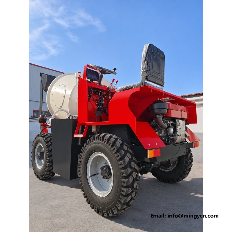
The hopper is not only a drum feeder. At full lift it reaches a height that lets the machine load a small truck bed or a barrow line directly, which is often how a mixer earns its keep on a site with separate casting points. The raised side photographs show the reach and the tipping angle, and they show whether the load leaves the hopper cleanly when the target sits beside the machine rather than behind it. A hopper that only works over its own drum does one job. Ask for one frame with the hopper tipped fully forward, because the discharge angle is the half of the geometry that lift height alone does not show. A hopper that discharges cleanly to the side also empties faster over its own drum, because the same wall angles work in both directions.
Full lift opens the front of the machine like a hatch, and that is the best moment to inspect what normally hides there. The photographs show the front crossmember, the steering ram, the hose runs to the axle and the lower part of the drum support. Look for hoses that hang below the frame line, for a steering ram exposed to a strike from the front wheel, and for any ledge where a stone could sit and rub. The clearance under the raised arm also shows how much structure is only visible in this position. Anything routed for appearance rather than clearance is visible here, because the panel that hides it is up in the air. A line that runs above the crossmember rather than below it is the one that survives a bucket dragged across the front.
A raised hopper is a stored load, and photographs of it should be read with that in mind. Nothing in a gallery tells you whether the lift circuit holds position without creep, so treat the raised arm as a hazard until you have tested it yourself: raise it, stop the engine, and watch for movement before going near the pivot. On the machine, the rams and any hose burst valves are the parts that decide whether the arm stays up. In the photographs, check that no one has replaced a burst protected line with a plain hose. Ask for the circuit diagram, and confirm which line carries the load. A machine without burst protection should be lowered with the hopper down and the circuit unpressurised, and that instruction belongs in the handbook.
The specification sheet does not quote a separate lift height, and this page will not invent one. What the photographs show is the relationship that matters: at full lift the hopper lip sits above the drum opening with margin for a tipped load to fall clear of the charging ring, and the arm reaches an angle that lets the machine load a small truck bed. If a specific lift height is critical to your site, ask for it measured from ground to lip.
It should not be. The lift circuit is designed for loading at a standstill, with the machine positioned close to the pile and the brake set. Raising a full hopper while rolling puts a moving load on the front axle and shortens the life of the pivot bushes. The safe sequence is position, stop, raise, tip, lower, then move. Photographs of the raised position are useful precisely because they show how far the load sits ahead of the axle.
For the current specification, build options and a formal quotation for your market, contact MINGYI Machinery. E-mail: sales@mingycn.com | LINE (ID): mingyicn
Loading Hopper and Lift Arm on the 1.5m3 Self Loading Mixer · 1.5 m3 Self Loading Concrete Mixer: Full Specification and Walkaround · 1.5m3 Self Loading Mixer from Every Angle: A Yard Photo Reference