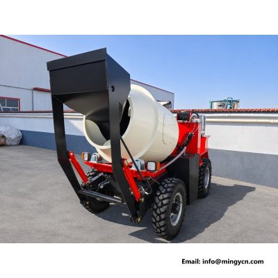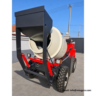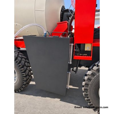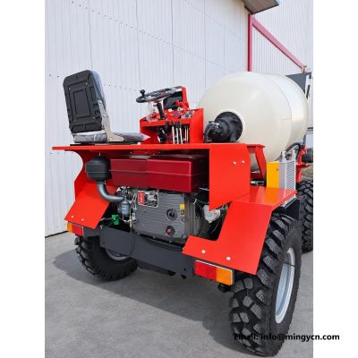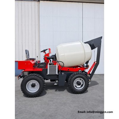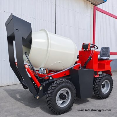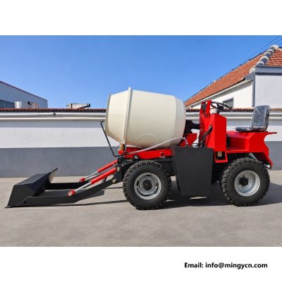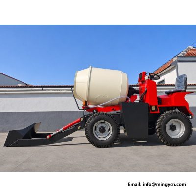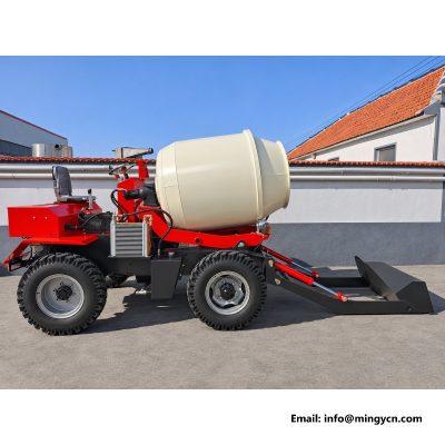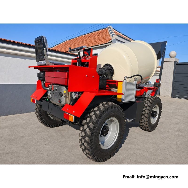
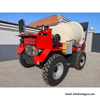
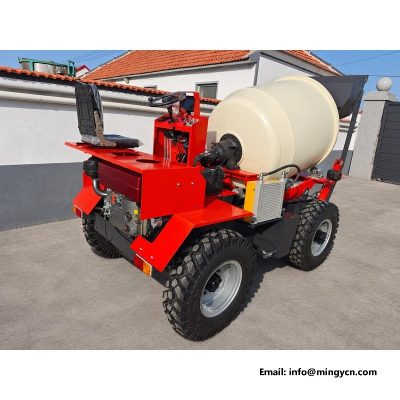
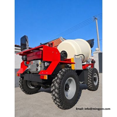
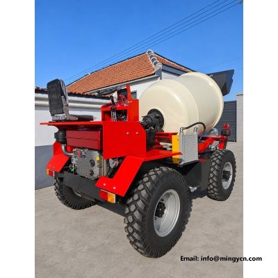
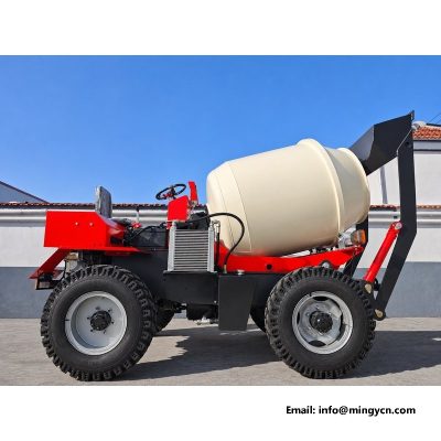
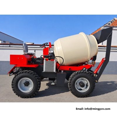
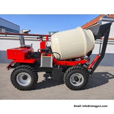
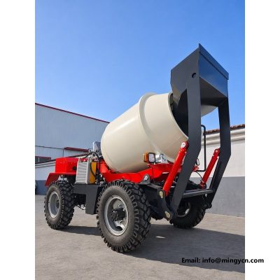
left rear and drum side: shell, lift arm and frame joints
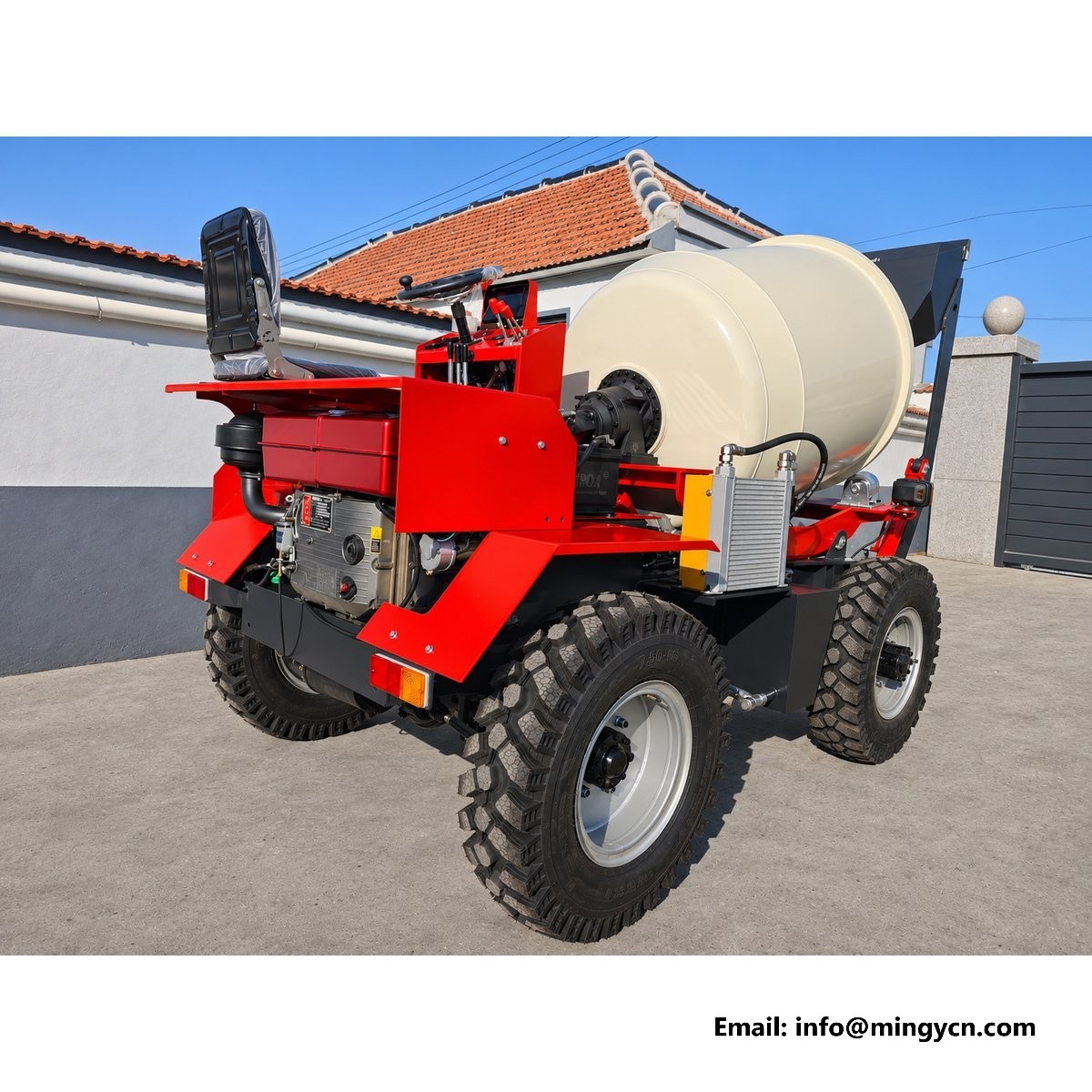
Three corners of a mixer get photographed for brochures. This set covers the fourth. The left rear frames the drum shell, the lift arm hinge and the frame joints from the side that carries tension rather than compression, and the light falls across the surfaces instead of along them, which is what you need to read a weld or a seam. The machine here is the 1.5 m3 build, with a 5,000 kg rated load, a 1,900 kg operating weight and a short tail behind the rear axle. What follows is a corner by corner reading of what this side shows, and why it is worth asking for.
| Specification | 1.5 m³ self loading mixer |
|---|---|
| Drum capacity | 1.5 m³ (1,500 L) |
| Overall dimensions (L x W x H) | 3,500 x 1,600 x 2,200 mm |
| Rear axle | 130 four-wheel steering |
The left rear is the corner nobody stages. Brochure photography favours the front quarter, where the hopper and the drum nose make a clean shape, and the left rear is usually left to whatever the camera caught. That makes it useful. On this set the left rear frames show the drum shell, the lift arm hinge and the frame joints without a flattering angle, and the light falls across the surfaces rather than along them. If a supplier is willing to publish this corner, the build is usually sound. The light here comes from behind the camera and slightly to one side, which shows a weld toe instead of hiding it under a highlight. Photograph the corner in shade as well as in sun, because shade removes the highlight that hides a crack line.
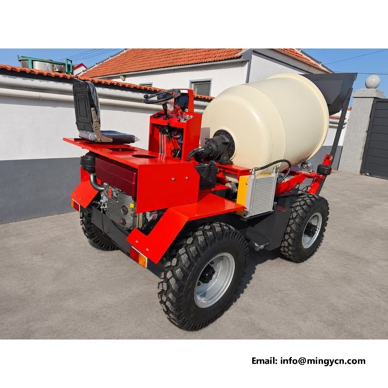
A mixer drum is a pressure vessel in everything but name, and the shell is where its shape is decided. From the left rear, the long seam should run straight along the barrel with an even weld, and any ribs should be rolled rather than welded on as flat bar. Look at where the cone meets the barrel. A smooth transition suggests the shell was formed in sections on rolls. A visible step suggests plate bent by hand. The shell should also be free of oil canning, the shallow dents that appear when thin plate is welded under tension. A shell that rings dull when tapped has a liner or a repair behind it. Look at the internal baffle if the drum is empty, because a baffle that has cracked away from the shell will show as a bright line on the outside.
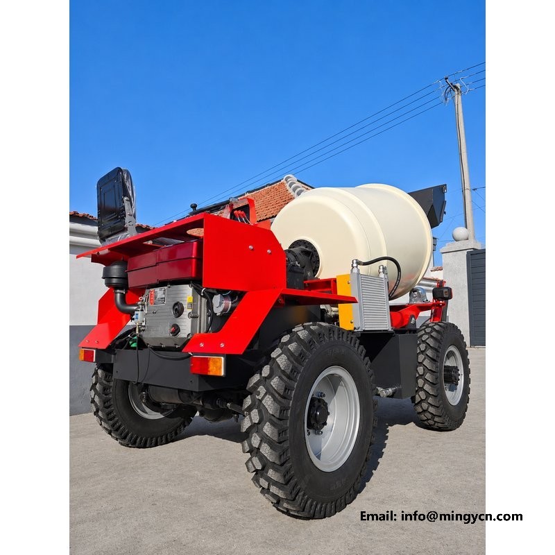
Paint on a drum wears in patterns, and the patterns are a service record. Polished strips along the barrel show where material slides. Scuffed patches near the mouth show where a shovel has been dragged. Rust bloom along a seam shows where water sits. On the left rear, look at the lower third of the shell, which is where wet mix collects and where the paint fails first. A machine that has been used will show these marks, and that is acceptable. What is not acceptable is fresh paint over a seam that has been welded. Wear concentrated in one band rather than spread along the barrel tells you how the drum has been run. A shell repainted all over is worth questioning, because paint over a working seam hides the one thing this corner is good at showing.
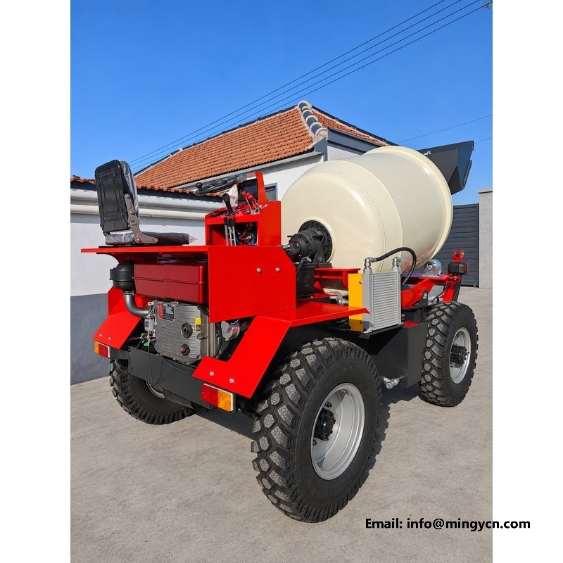
From the left rear the lift arm hinge is visible from the side that takes the tension. The arm pulls the hopper up and back, so the rear face of the pivot boss carries the load when the bucket is full. In the photograph, look at the boss. It should be a machined tube welded through the riser plate, not a short collar welded on the outside. Check pin retention, the grease point and the clearance between arm and riser through the full arc. A hinge with a bright wear ring around the boss has been working with a dry bush. A boss bored after welding shows a machined face around the pin, and that face is what keeps the arm from working sideways.
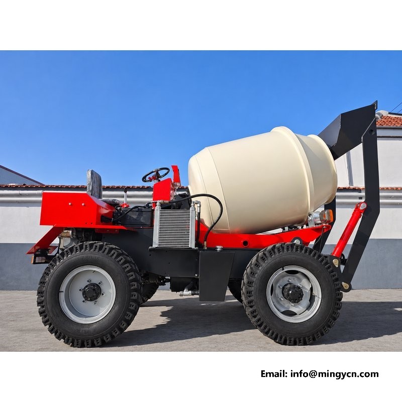
Weld quality is easiest to judge where two planes meet at an angle, and the rear left corner of the frame has several of those. Look at the toe of each weld, the line where the weld meets the parent plate. A clean toe with a slight concave profile spreads stress. A toe with undercut, a groove melted into the plate beside the weld, concentrates it. On the frame rails, check that vertical and horizontal welds meet without a crater, because a crater at a corner is where a crack begins. Look also at the stiffener where a crossmember meets the rail, because that joint takes the twist when one rear wheel climbs. Run a finger along the toe if the machine is available, because a toe that catches a nail is a toe that will crack.
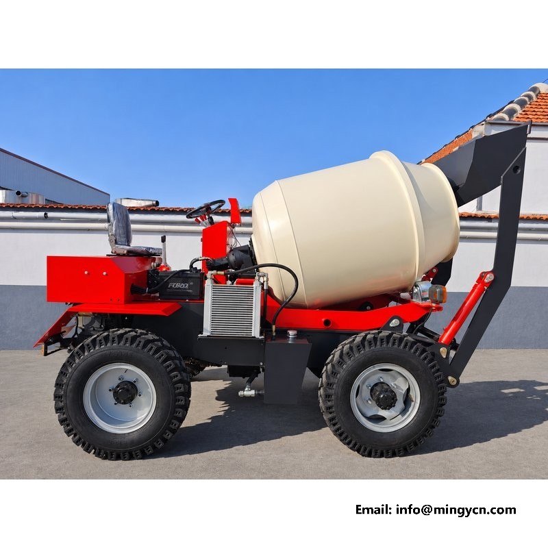
The gap between drum shell and frame rail can be read from the left rear, and it should be even along the length of the drum. An uneven gap means the drum is not sitting square on its saddle, which usually traces back to a mounting plate shimmed on one side or a shell that is out of round. Check the gap at the front, the middle and the rear of the drum in one photograph. Where the gap closes to nothing, the drum will touch the frame under load. A gap that is even at the top and closed at the bottom means the saddle is sitting on a high spot, and the drum will work against it. A drum that has been removed and refitted often sits high on one side, and the gap shows it before the bolts do.
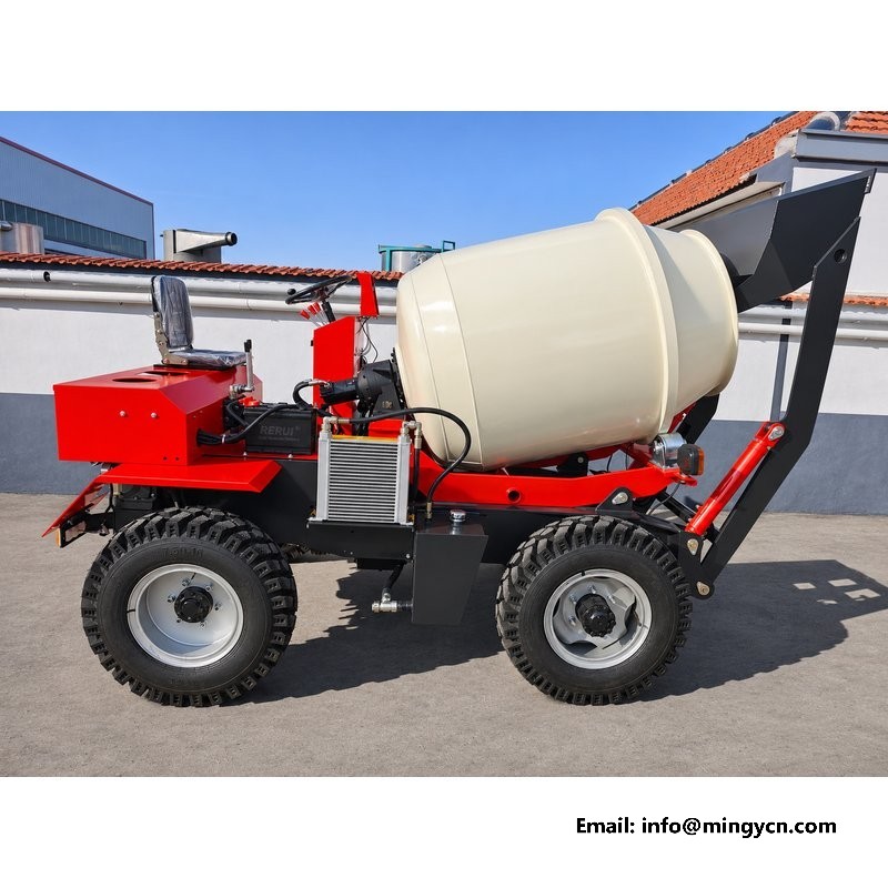
The drum drive sits at the rear of the drum on this layout, and the left rear is where you see whether it can be serviced. Look for a guard that comes off with a spanner rather than a grinder, for a chain case or gear case with a drain and a level plug, and for enough clearance to get a hand to the adjustment point. A drive buried behind the frame and under the drum is a drive that runs until it fails. In the photographs, the useful detail is the space around the guard rather than the guard itself. Ask whether the case has a drain, because a chain case that collects condensate rusts the chain first. A guard with a hinge is better than one with four bolts, because the guard that is easy to open is the one that gets checked.
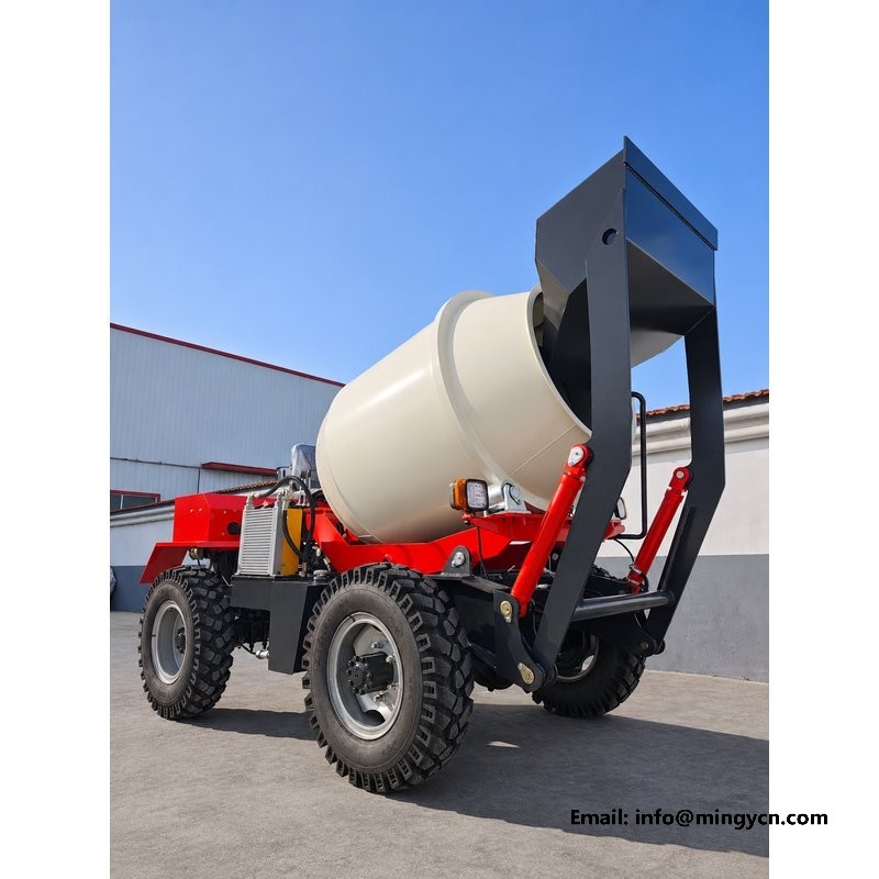
The left rear carries the hoses that serve the lift rams and the rear steering, and this corner shows them in profile. Look at how each hose leaves the frame: a gradual bend, a clip within a short distance of the fitting, and a sleeve wherever it passes a plate edge. A hose that drops straight out of a fitting and then turns is being worked at the crimp every time the arm moves. Check also that the bundle passes outside the drum guard rather than between guard and shell, where a loose hose can be pinched as the drum turns. A hose clipped to the guard moves every time the guard comes off. Look for a hose that crosses another without a separator, because two hoses rubbing together fail where nobody looks.
When a machine has been used, the left rear shows how it has been repaired, and the difference between a bolted patch and a welded one is worth reading. A bolted patch on a frame is usually a field fix made without power, and it can be sound if the plate is thick and the bolts are graded. A welded repair is stronger and harder to judge, because a weld laid over a crack without cutting back to sound metal will fail again. In the photographs, look for plate overlapping a joint, for bolt heads of mixed sizes, and for paint applied over a weld without primer. A plate bolted through a rail web crushes the web when the bolts are tightened.
The left rear is the corner to photograph again after a season of work, because it accumulates evidence. Take the same frame, from the same height, with the drum in the same position, and compare. Wear at the hinge, a widened gap at the drum saddle, a new oil trail from the drive guard and paint loss along a weld toe will all appear in the same places. A supplier who can produce a second photograph of the same machine after a year on site is telling you more than any brochure. Keep the two frames side by side on one screen, because a change of a few millimetres at a hinge is invisible in isolation. Date the second frame and note the working hours if the operator keeps a log, because wear means more when it is set against use.
Because it is the corner that shows structure rather than styling. The left rear puts the drum seam, the lift arm hinge and the frame joints in one frame, under light that reveals weld toes and paint condition. A supplier who publishes it is usually confident about the build. A gallery that only shows the front quarter and the drum nose is not necessarily hiding anything, but it is not showing you the parts that fail either.
Partly. A sharp frame taken in raking light will show a weld toe, undercut and crater, which are the three things that predict a crack. It will not show penetration, porosity under the surface or the grade of the filler metal. Use the photograph to decide whether the build is worth inspecting, then ask for the weld procedure and the inspection record if the machine is going onto a site where a structural failure would stop the pour.
For the current specification, build options and a formal quotation for your market, contact MINGYI Machinery. E-mail: sales@mingycn.com | LINE (ID): mingyicn
Welded Chassis Frame on the 1.5m3 Self Loading Mixer · Mixing Blades and Drum Interior on the 1.5m3 Self Loading Mixer · 1.5m3 Self Loading Mixer from Every Angle: A Yard Photo Reference