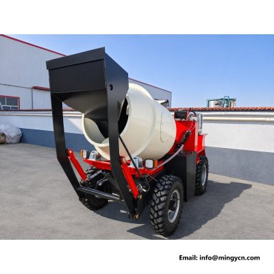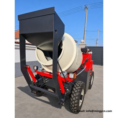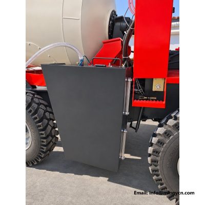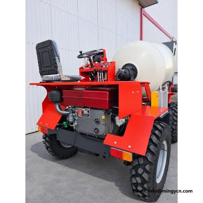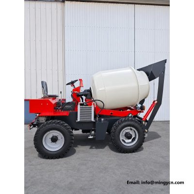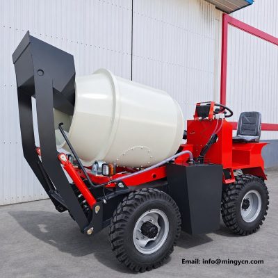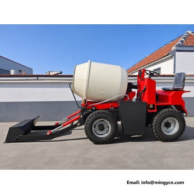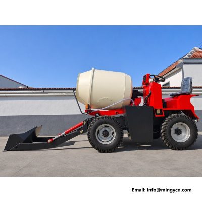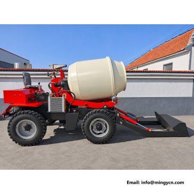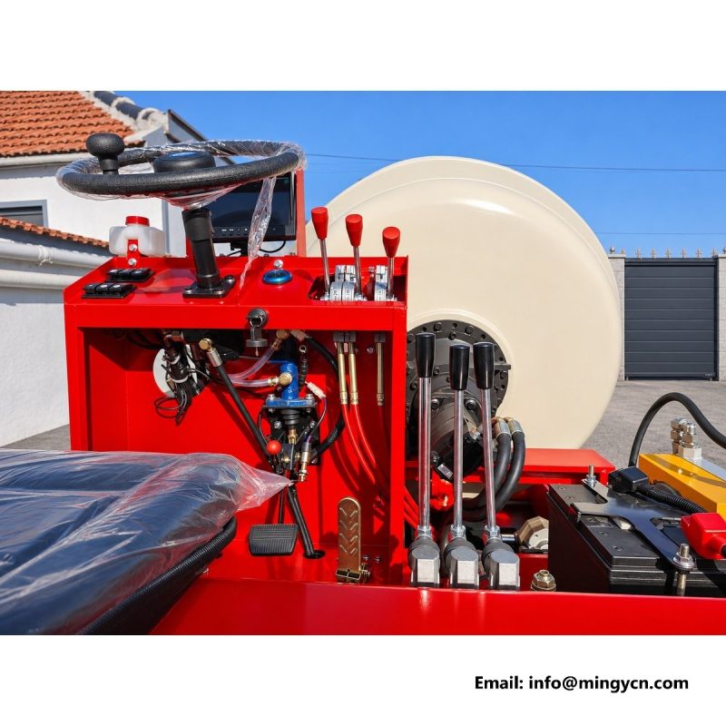
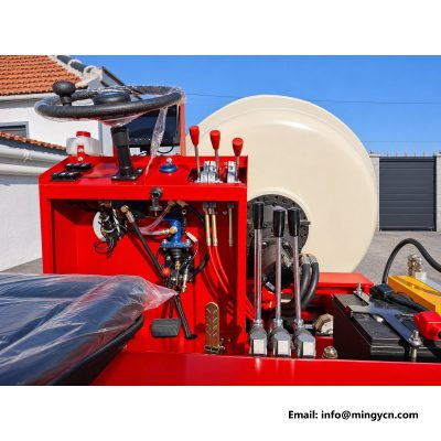
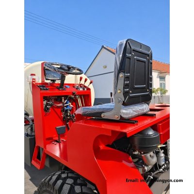
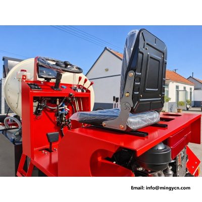
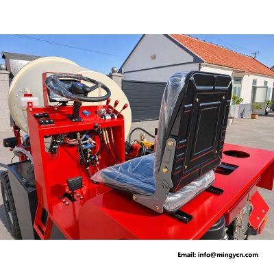
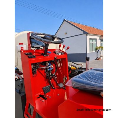
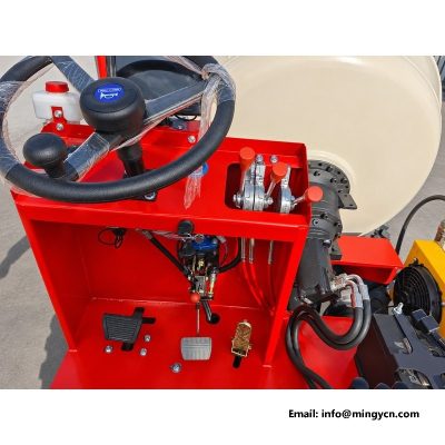
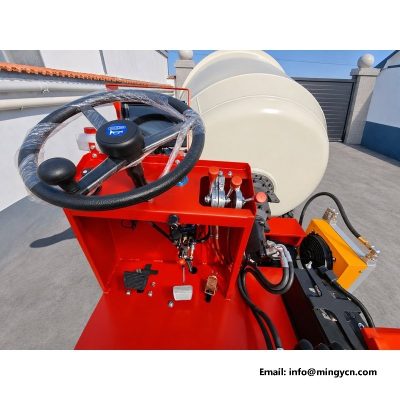
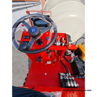
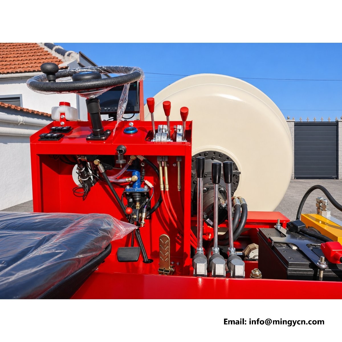
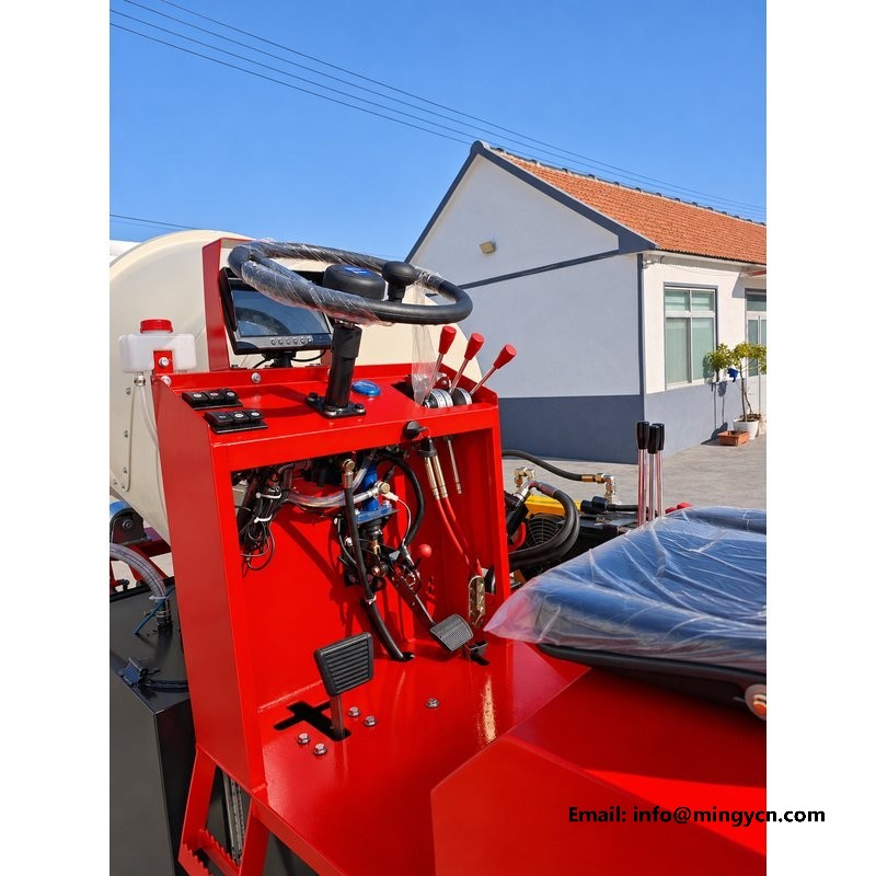
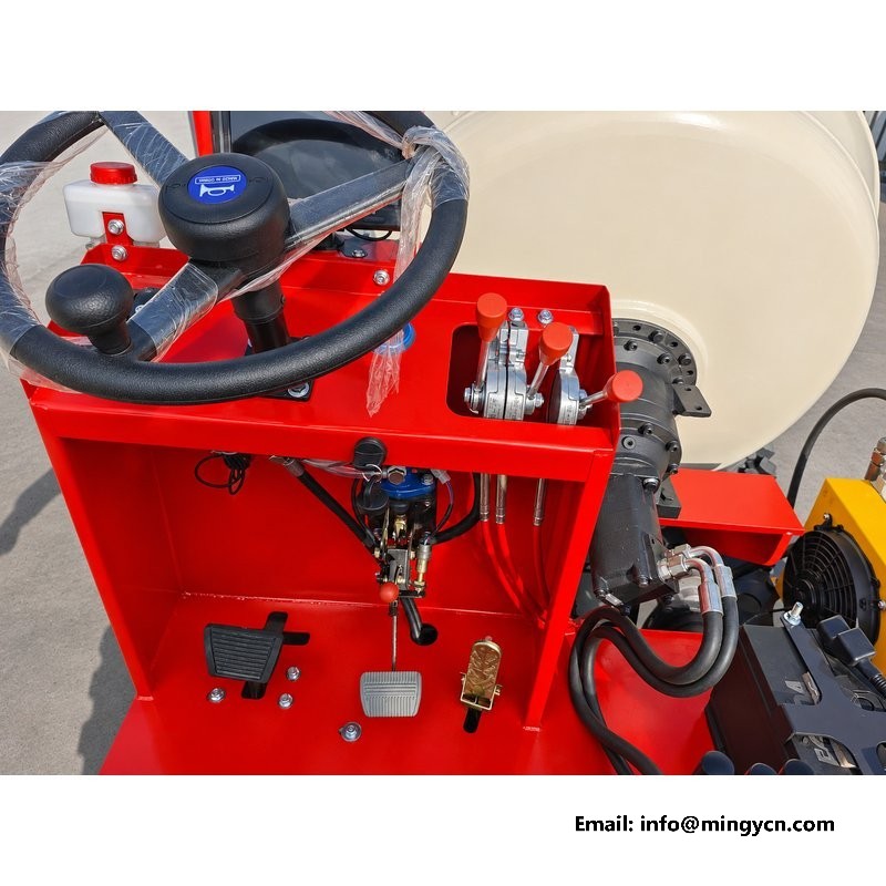
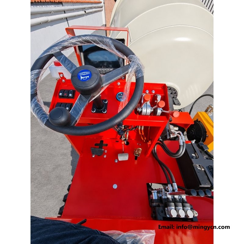
steering wheel and lever bank: control layout close-up
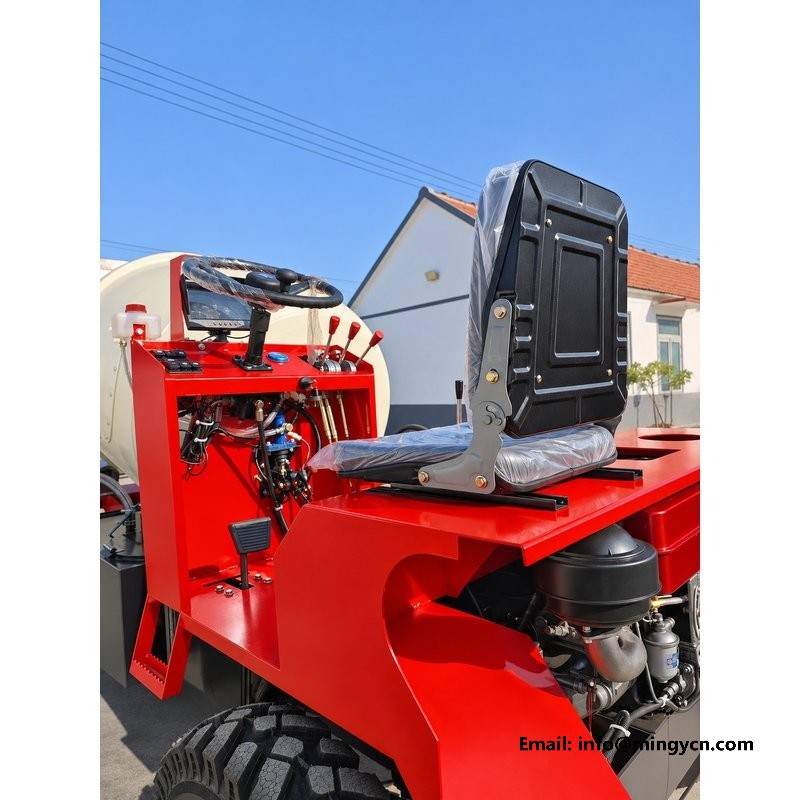
Control layout is one of the few things a buyer can judge properly from photographs, because it is entirely a matter of position. These eight frames were taken at the operator station of the 1.5 m3 self loading mixer: the wheel from several angles, the lever bank from above and from the side, the instrument panel with the ignition on, and the seat in relation to both. What follows reads the layout the way an operator would after a long shift, asking where the hands fall, what the eyes can see without turning, and which controls are worked by feel rather than by sight.
| Specification | 1.5 m³ self loading mixer |
|---|---|
| Steering angle | 28 degrees |
| Turning circle (outer tyre) | 2,464 mm |
| Transmission | 4WD, 3 forward + 1 reverse + road gear |
| Steering | Hydraulic power steering |
These photographs were taken from the operator position rather than at it, which is the only honest way to judge a control layout. Everything the driver touches falls into two zones: the wheel ahead of the chest and the lever bank under the right hand, with the gauge panel set slightly left of centre so the needle stays in peripheral vision while the shovel is working. Nothing sits behind the shoulder and nothing demands a twist of the spine. That sounds minor until a shift involves a batch every few minutes. A control that needs an awkward reach is a control operated late, and a lever worked late shows up as a spilled pour at the drum mouth. Read these frames as a map of reach rather than a list of features.
The wheel is a plain three-spoke pattern with a thick rim, and the close frames show why that matters. The rim section is deep enough for a full hand grip through work gloves, and the spoke layout leaves the lower half open so the driver can see the hub and the column shroud without ducking. Column angle is set closer to a truck than to a car, which keeps the forearms low and the shoulders relaxed during long spells of shuttling. The wheel is not overloaded with buttons, and that is deliberate. On a site machine a horn pad and a turn of the wrist are worth more than a cluster of switches nobody can find while wearing gloves. Check whether the rim is moulded over the metal or clipped on. A clipped rim develops play at the spokes long before the steering itself does.
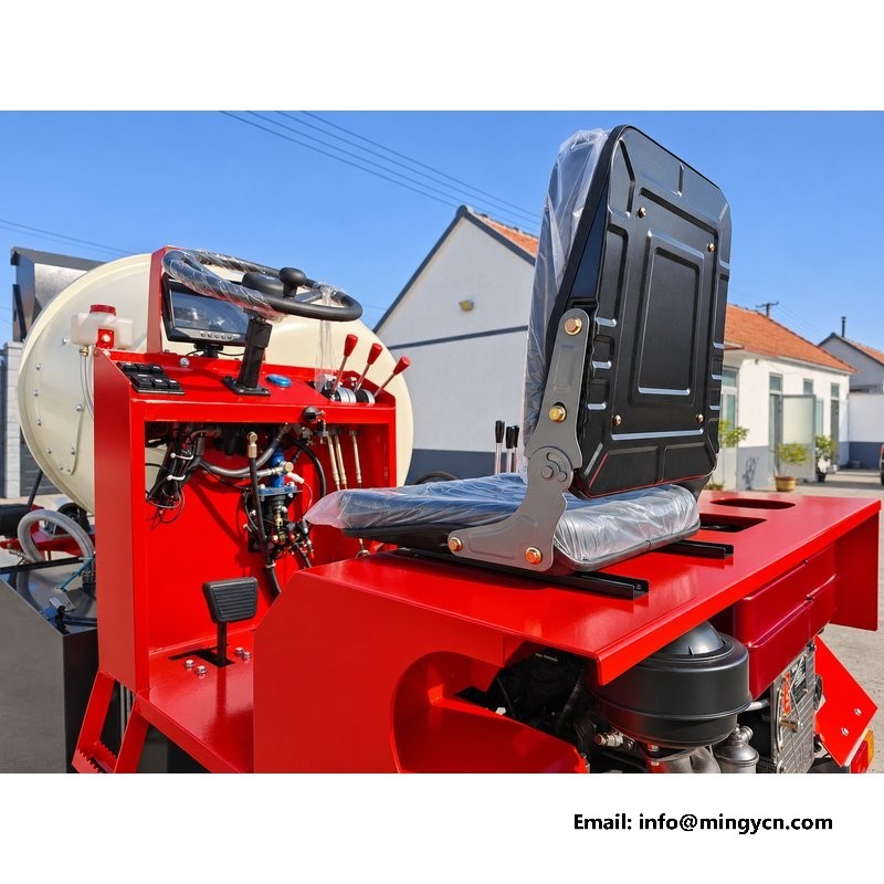
Power assistance is not a luxury on a machine that carries a full drum behind the front axle. The photographs of the steering column and the front axle show the ram and the steering arms, and the layout explains the effort at the rim. With hydraulic assistance a loaded machine can be turned at walking pace with one hand, which is exactly the condition that matters when the shovel is in a stockpile and the operator needs to reposition without leaving the seat. Read the hose runs from the column down to the axle in the wider frames. They should travel in a protected route, away from the tyre envelope and clear of the lift arm sweep. A hose that crosses the steering arc is a hose that will be rubbed through in a season of tight yards.
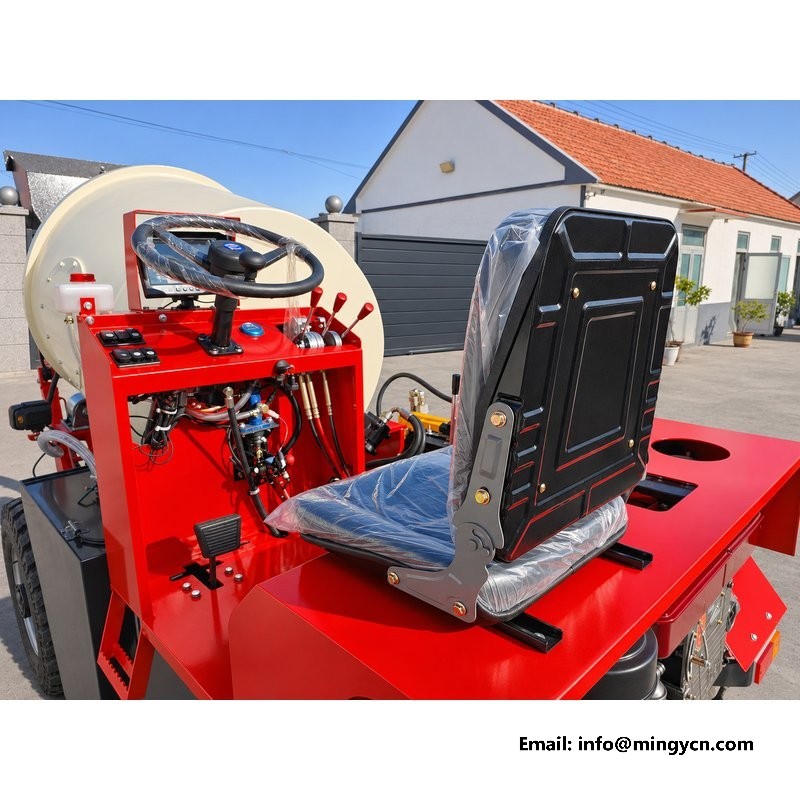
The lever bank is where most self loading mixers become confusing, so the close-ups here are worth studying. Each handle sits at a different height and angle, and the layout groups travel controls apart from the loading and mixing functions. That separation is what lets an operator work the shovel and the drum without looking down at the bank every time. Feel matters as much as position. A lever with a positive detent at neutral returns to centre when released; a lever with a soft gate drifts and the function creeps. In the photographs, look at the boots at the base of each lever. A moulded boot that seals against the console keeps grit out of the linkage, and grit in a linkage is the usual reason a lever starts to feel vague after a few months of site work.
The transmission is a four-wheel-drive unit with three forward ranges, one reverse and a road gear, and the selector sits where the left hand falls naturally. That arrangement separates two jobs that are often muddled on cheaper machines: choosing a range for torque, and choosing a gear for travel speed. Loading happens in the low ranges, where the machine creeps and the hydraulics have priority; the road gear exists for moving between sites, capped at 24 km/h. In the photographs the gate pattern should be visible and the positions should be marked rather than implied. A selector with an unmarked gate invites the operator to find reverse by trial, and finding reverse by trial beside a trench wall is not a habit worth encouraging.
The instrument panel is small, and that is the point. What matters is whether the few instruments present can be read at a glance from the working position. The frames here show the dial faces angled towards the driver rather than flat in the dash, which reduces reflection from the sky and keeps the needles legible in bright yards. Coolant temperature, hydraulic oil temperature and battery charge are the readings that decide whether a shift continues or stops, and they should sit together rather than scattered across the panel. Warning lamps should be visible without shading them with a hand. Ask for a photograph taken with the ignition on. A panel that only appears in a studio shot with the key out tells a buyer nothing about whether the lamps actually illuminate.
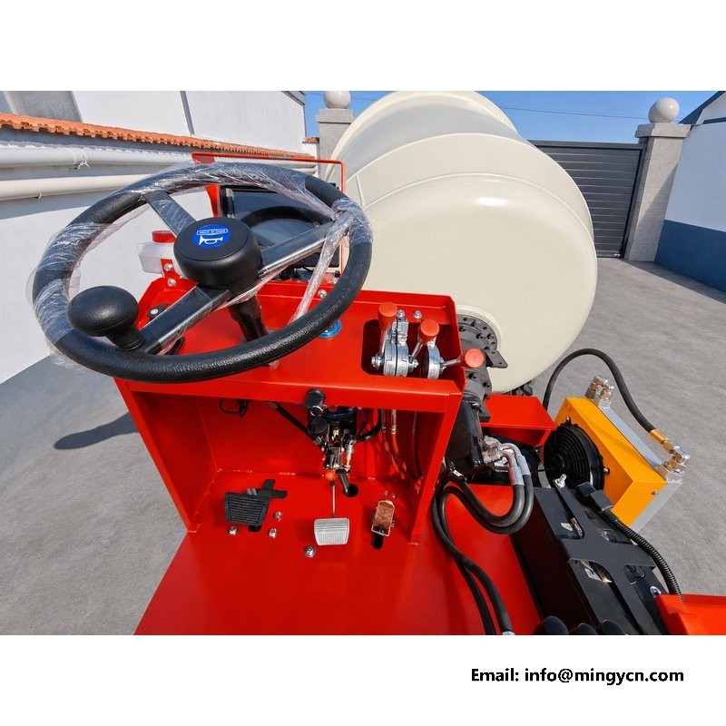
Around the lever bank and the column there is a small set of switches, and their placement says more about the design than their number. Horn, lights and the engine stop belong within reach of a hand that is already on a lever, because those are the functions demanded in a hurry. Everything else can sit further away. In the photographs, note whether the switches are flush or proud of the panel. Flush switches catch less on a sleeve but are harder to find by touch; proud switches are easier to locate but collect mud and get knocked. Either choice is defensible if it is consistent. What is not defensible is a mixture that puts the stop control out of reach while a rarely used work lamp sits under the thumb.
The steering geometry is the part of the layout that photographs explain best. The front axle steers through 28 degrees, and the rear axle is a four-wheel-steering unit that turns as well, which is how a machine of this length works inside a turning circle of 2,464 mm. In the yard frames, look at the tie rods and the steering arms at both ends. The rear linkage is exposed behind the frame, and it should be high enough to clear ruts and guarded against the tyre. A four-wheel-steering machine with an unprotected rear linkage is a machine that will lose its steering in a wet yard. Look also at how the rear wheels sit relative to the frame: the track should read as a straight line down the side.
A single-cylinder diesel under the seat sets the ergonomic problem for the whole machine. It is a simple, easily serviced engine, and it also produces a steady low-frequency shake that a driver feels through the floor and the wheel. The photographs show the seat mounting and the isolation between the platform and the frame, and those details are the answer to the vibration question. A seat on a suspended base with a firm backrest keeps the spine off the end stops over a long shift. The wheel should be reachable with the shoulders against the backrest, not by leaning forward. Arms should fall to the levers without stretching. Where only pictures are available, judge the distances: knee room, elbow room, and whether the levers sit where a relaxed hand lands.
Photographs settle layout questions and leave feel questions open, and a buyer should be clear about the difference. These frames show where the wheel sits, how the levers are grouped, what the panel displays and how much room the operator has. They cannot show how heavy the steering is at a standstill, how much the levers resist, or how loud the engine becomes under load. Those need a demonstration, or at least a video with sound. Ask the supplier for a short clip of the machine cycling the shovel and tipping the drum, filmed from the seat. Ask whether the steering effort was checked with a full drum. And ask which controls are mechanical linkages and which are hydraulic pilots, because that answer decides how the machine will feel after a few thousand hours.
Position yes, feel no. The frames show where each handle sits relative to the wheel and the seat, which is enough to judge reach and grouping. They cannot show resistance, detent quality, or how the linkage behaves when the oil is still cold at the start of a shift. Ask for a short video filmed from the seat during a full working cycle, and watch how often the operator has to look down at the bank.
The working ranges keep the machine slow and the hydraulics strong while loading. The road gear is for moving between sites and is limited to 24 km/h. Separating the two means the operator does not have to compromise between torque in the pile and speed on the track, and the transmission is not worked outside its purpose on either job. That separation also makes the selector easier to teach to a new driver.
For the current specification, build options and a formal quotation for your market, contact MINGYI Machinery. E-mail: sales@mingycn.com | LINE (ID): mingyicn
Operator Station: Steering, Seat and Control Levers on the 1.5m3 Mixer · 1.5 m3 Self Loading Concrete Mixer: Full Specification and Walkaround · Reversing Camera Display at the Operator Station of the 1.5m3 Mixer