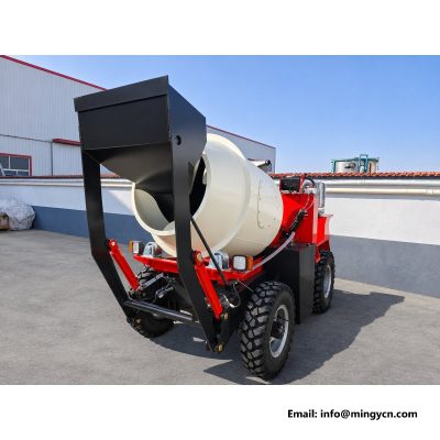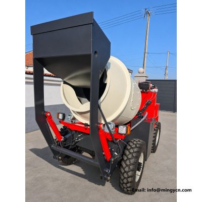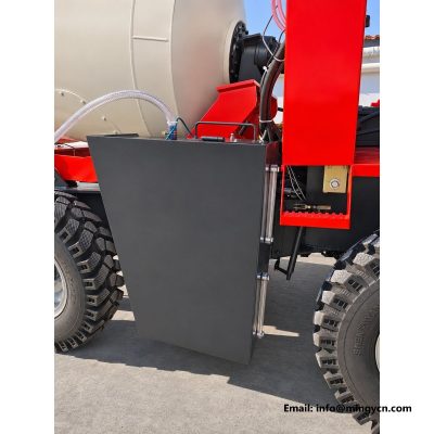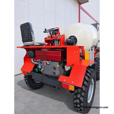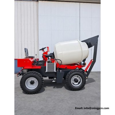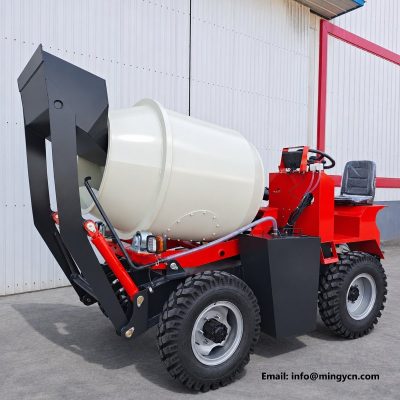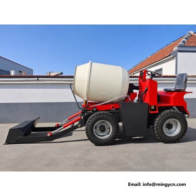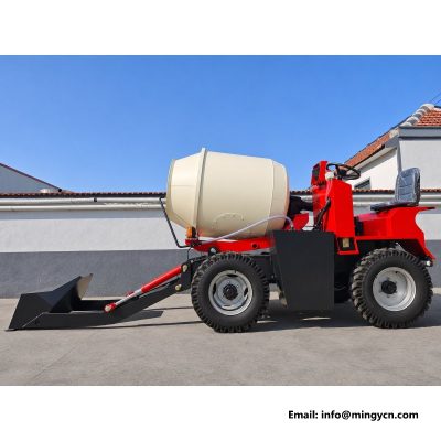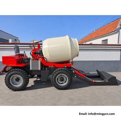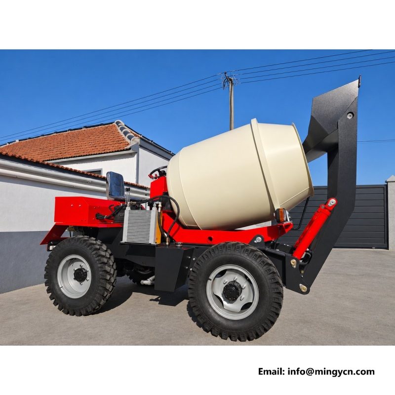
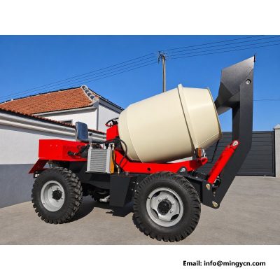
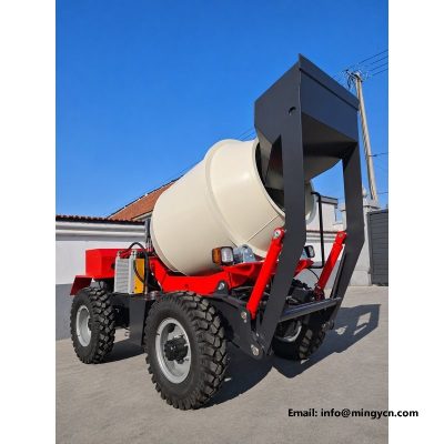
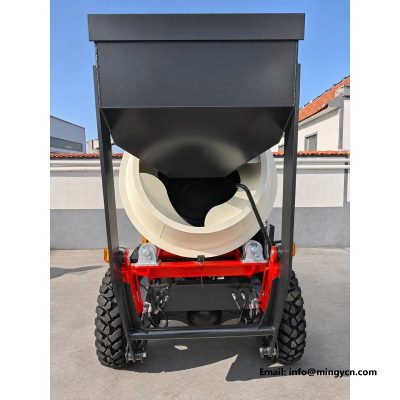
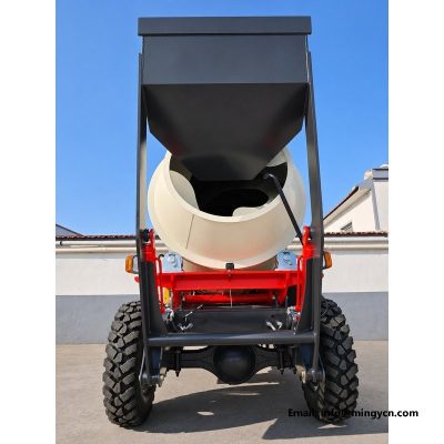
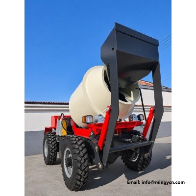
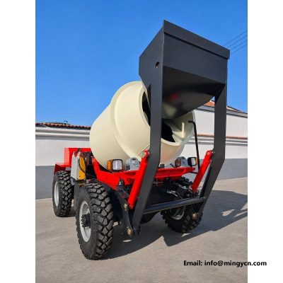
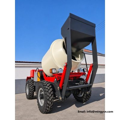
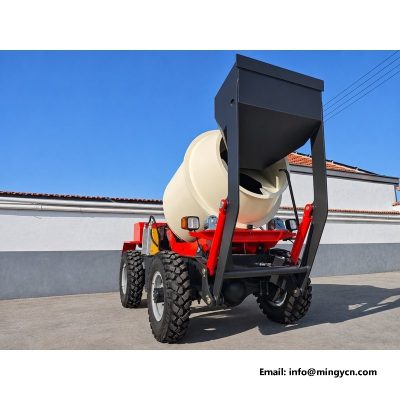
bucket lowered: ground level photos of the 1.5m3 mixer
A self loading mixer spends most of its working life with the bucket down, yet most photographs show it raised. This set corrects that. The eight frames below show the machine with the lift arms at the bottom of their stroke and the bucket resting on the ground, photographed from the side, from the front quarter and from ground level. From those angles the loading geometry can be read directly: where the mouth sits, how the cutting edge meets the ground, how the arms and rams rest, and what the machine looks like in its travel posture. The commentary stays with what the images show.
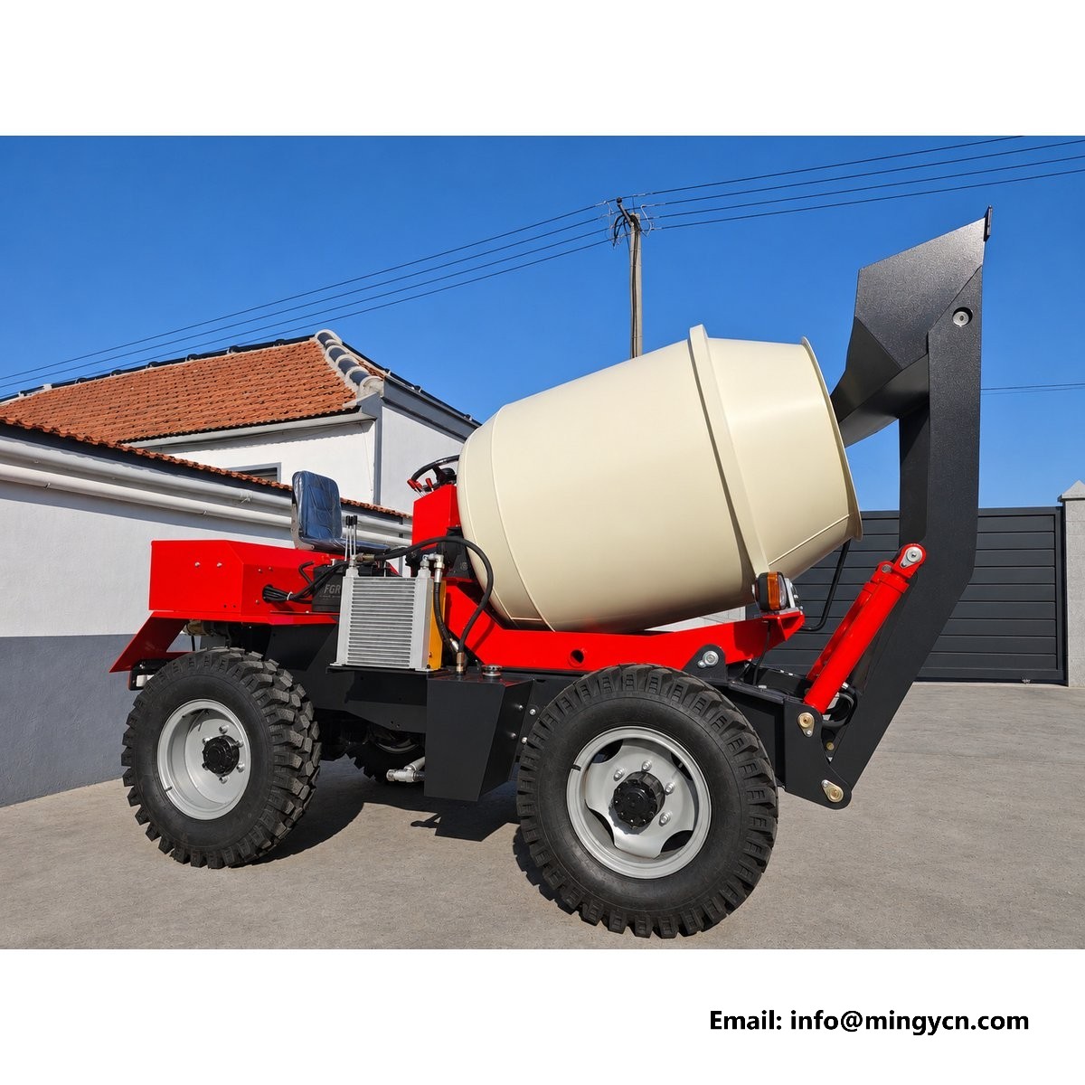
| Specification | 1.5 m³ self loading mixer |
|---|---|
| Rated load | 5,000 kg |
| Overall dimensions (L x W x H) | 3,500 x 1,600 x 2,200 mm |
| Minimum ground clearance | 204 mm |
Most sales photographs show a self loading mixer with the shovel raised, because a raised arm looks dramatic and fills the frame. It also hides the part of the machine that decides how well it loads. These frames do the opposite: the bucket is on the ground, the lift arms are at the bottom of their stroke, and the geometry between the cutting edge, the ground and the front axle can be read directly. That is the posture the machine spends most of its working life in, scooping sand, gravel and aggregate out of a stockpile. A buyer who studies this position learns more about loading behaviour than from any three-quarter shot with the arm in the air, because everything that governs the bite is visible at once and nothing is foreshortened.
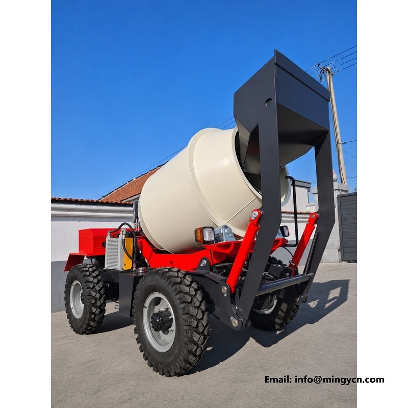
With the arms fully lowered, the mouth of the bucket sits close to the ground, and the frames here show the gap clearly against the tyre contact patch. That gap is the first thing to judge. A mouth that hangs high leaves a ridge of material behind on every pass, and the operator compensates by crowding the pile, which loads the front axle and the arms harder than they need to be worked. A mouth low enough to skim the surface but not so low that the lip digs into the yard scrapes cleanly and leaves a flat floor. Look at the photograph taken square to the side: the line of the cutting edge against the ground line tells you whether the bucket is level at rest, and whether the linkage keeps it level through the first part of the lift.
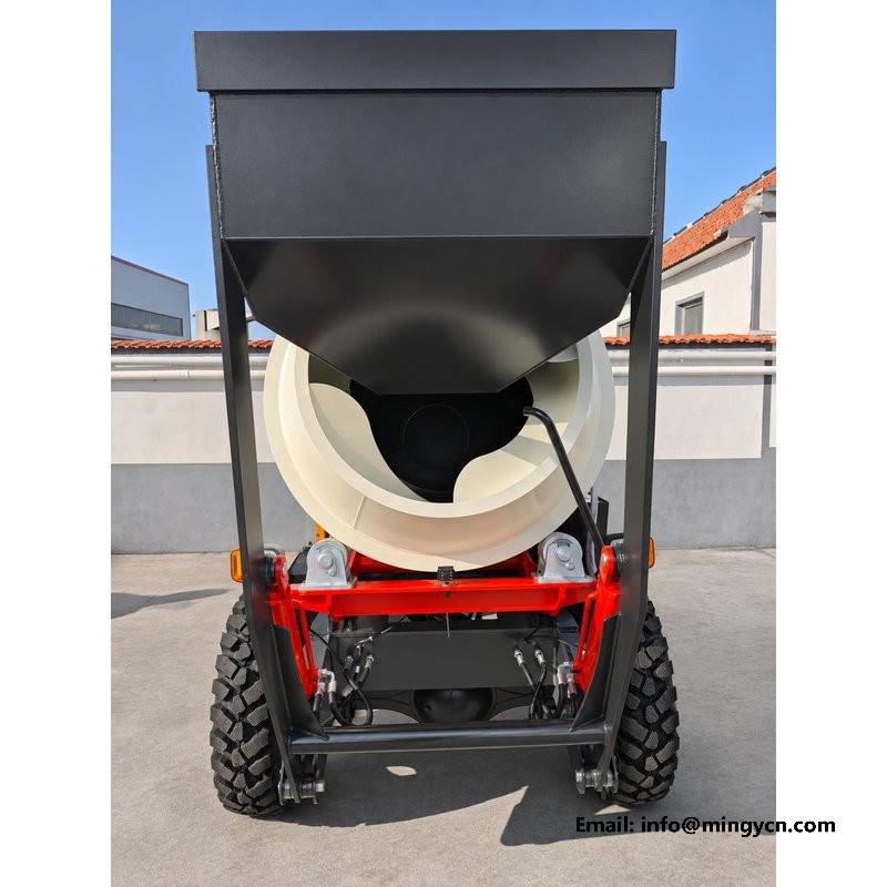
The angle at which the cutting edge meets the ground decides how the bucket fills. Too steep and the machine rides up over the pile instead of cutting into it; too shallow and the edge skates across the surface, polishing the material rather than scooping it. The ground-level frames are the only ones that show this angle honestly, because the camera is at the same height as the work. Look at the underside of the lip and the wear strip behind it. A reinforced edge with a visible wear plate can be rebuilt; a plain folded lip cannot, and it wears through at the corners first. Look also at how the side plates are cut. A bucket with a slight taper at the sides releases material cleanly when tipped, while a parallel box holds damp sand against the walls.
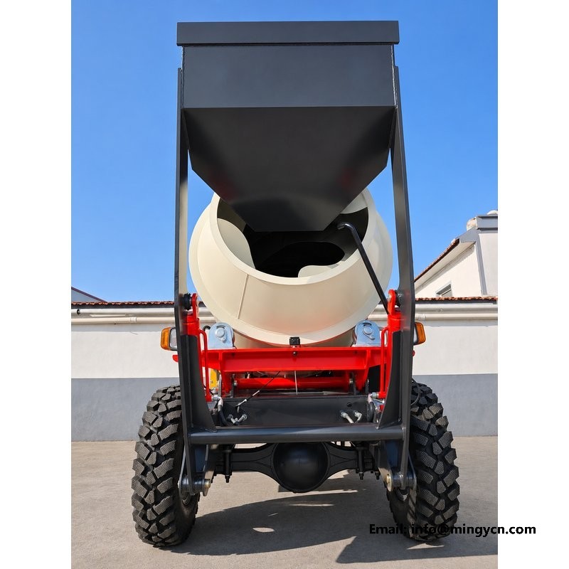
The floor of the bucket takes the most abrasive work on the whole machine, and the lowered position is the only time it can be photographed properly. In these frames the underside is visible, including the wear strips and the way they are attached. Strips laid across the floor take the sliding abrasion and can be replaced; a floor that relies on plate thickness alone will thin from the middle outward. Check the transition where the floor meets the back sheet. That corner collects damp material and is where corrosion begins on a machine working in wet conditions. A smooth fillet weld there, with no gap for grit to lodge, is worth more than a thicker plate elsewhere. Look also for drainage, so a bucket left standing in the rain does not hold water.
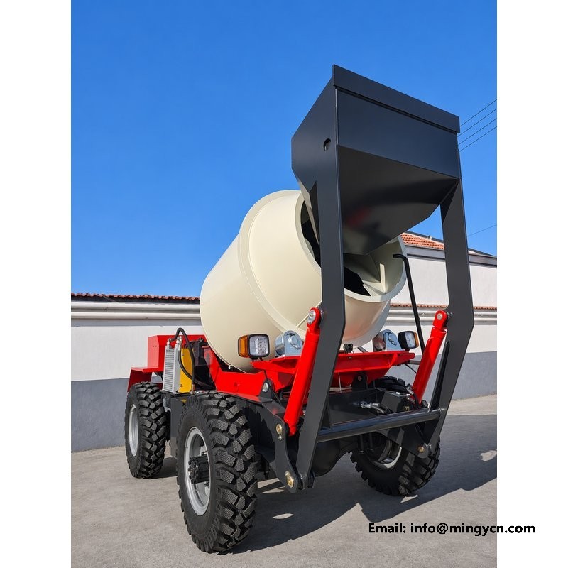
At the bottom of the stroke the lift arms lie almost parallel to the ground, and the photographs show the pivot bosses and the arm section in their least favourable position. This is where a light arm bends. With the bucket on the ground and the machine pushing into a pile, the arm acts as a beam with its load at the far end and its support at the pivot, and the bending moment is highest exactly here. Look at the depth of the arm section and whether it is a fabricated box or a pair of plates with a spacer. A fabricated box with continuous welds along both sides resists twist; plates bolted together flex and work their fasteners loose. The frames also show the cross tube that ties the arms, which keeps them moving as a pair.
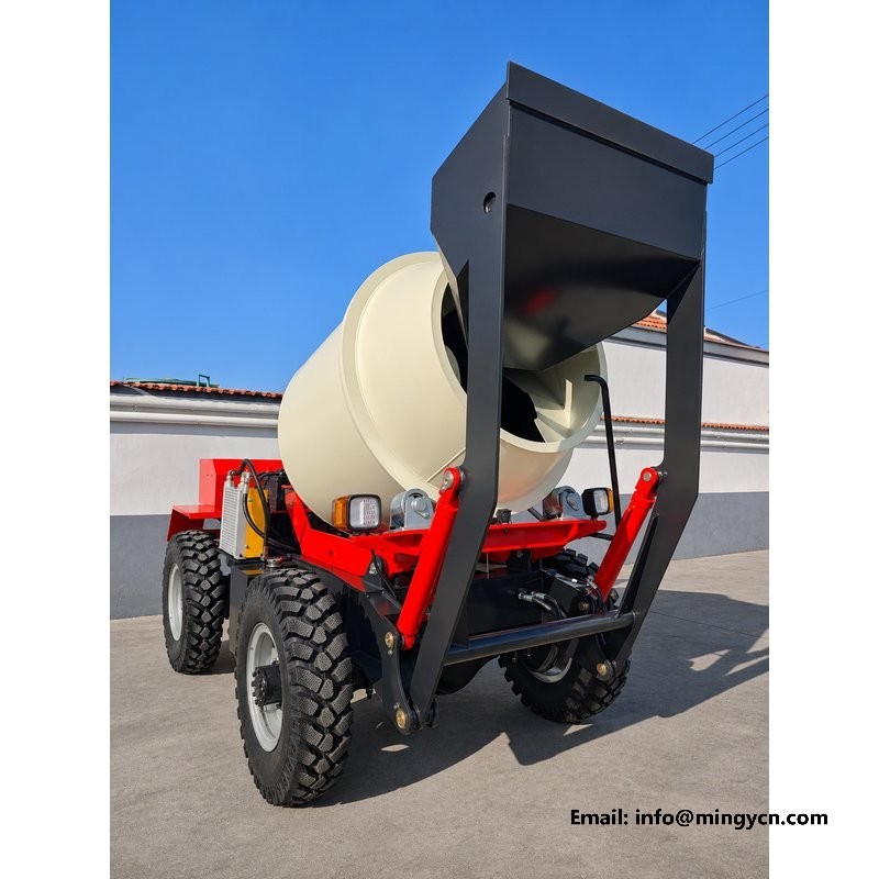
With the arms down, the lift rams are fully retracted, and the photograph shows the rod inside the barrel with the gland and the wiper seal exposed. That is a useful detail for a buyer. A retracted rod is a protected rod; an extended rod is the part that collects grit and carries it back through the seal. Machines that spend their life with the arms raised between loads wear their seals faster than machines that set the bucket down. Look at the hose loops at the rod end. They should hang in a natural curve with enough slack for the full stroke and no chance of being pinched between the arm and the frame. A hose pulled tight at the bottom of the stroke will be stretched at the top, and a stretched hose fails at the crimp.
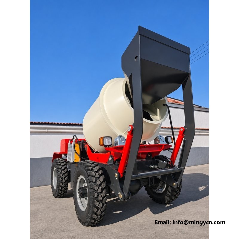
Ground clearance of 204 mm means something only when it is read together with the approach angle at the front. These ground-level frames show both. The bucket lip sits ahead of the front axle, and when it is lowered for loading the effective approach angle becomes very shallow, which is why the machine should be driven into a pile rather than up onto it. Look at what hangs lowest under the front frame: the axle, the steering linkage, the hose runs. On a site with rubble and broken kerbs, the lowest point decides whether the machine crosses a heap or bellies on it. The photographs should show a clean underside, with nothing dangling below the axle line and no hose loop hanging where a stone can hook it.
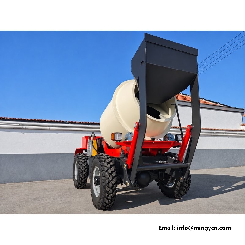
The tyres are 750-16 at both ends, and in the lowered-bucket frames the sidewalls show how much of the contact patch is doing the work. With the bucket down and empty, the front axle carries the arm and bucket assembly ahead of it, and the sidewall bulge at the front tells you how much of the 1,900 kg operating weight is standing on that end. Compare the front and rear sidewalls in the side-on frames. A machine with a heavy front bias steers well loaded but sinks in soft ground; a balanced machine floats better. Look also at the tread pattern and the rim offset. The rims should sit inside the 1,600 mm overall width, with the tyre shoulders protected by the frame rather than proud of it.
The way the bucket is carried between jobs matters more than most buyers expect. Travelling with the arms raised puts the load high and forward, which is exactly where a machine should not carry mass on a rough track. The photographs here show the arms lowered with the bucket just clear of the ground, which is the correct travel posture: low centre of gravity, the bucket acting as a bumper, and the front axle loaded moderately rather than fully. At the road gear limit of 24 km/h, that posture is the difference between a stable machine and one that pitches. Look for a transport position marked on the arm, and check whether the hydraulic circuit holds the arms up when the engine is switched off. A machine that settles overnight has a leaking valve.
Ground-level photographs are the closest thing to a pre-purchase inspection a buyer can get at a distance. Read them in a fixed order: bucket mouth to ground, cutting edge angle, floor wear, arm position, ram extension, clearance under the frame, tyre contact. That sequence follows the load path from the pile into the chassis, and it exposes the parts that are usually photographed least. Then compare the frames for consistency. If the bucket sits level in one shot and nose-down in another, ask why. If the arms rest at different heights on the two sides, the linkage is out of adjustment. A supplier who sends a set taken from the same height, at the same distance, on flat ground understands what a buyer needs to see.
Because that is the loading posture. With the arms down, the mouth height, the cutting edge angle and the arm position can all be read against the ground line. Raised-arm photographs hide exactly the geometry that decides how well the bucket fills, how the machine behaves in a stockpile, and how much load the front axle is asked to carry through the arms. One ground-level frame is worth a page of studio shots.
The chassis clearance stays at 204 mm, but the effective approach at the front becomes much shallower because the bucket lip now sits ahead of the axle near ground level. That is why the machine should be driven into a pile rather than up over it, and why the lip is the part most likely to catch on a kerb, a step or the edge of a stockpile.
For the current specification, build options and a formal quotation for your market, contact MINGYI Machinery. E-mail: sales@mingycn.com | LINE (ID): mingyicn
Loading Hopper and Lift Arm on the 1.5m3 Self Loading Mixer · 1.5 m3 Self Loading Concrete Mixer: Full Specification and Walkaround · 1.5m3 Self Loading Mixer from Every Angle: A Yard Photo Reference