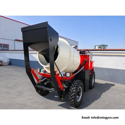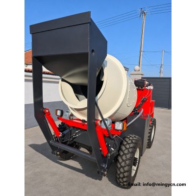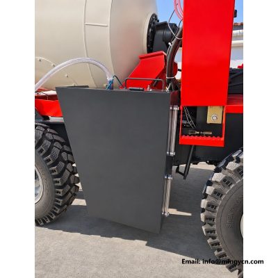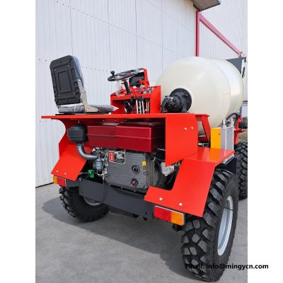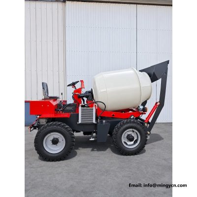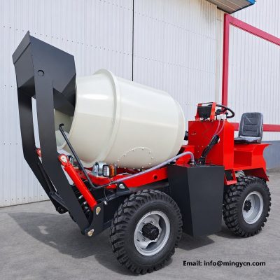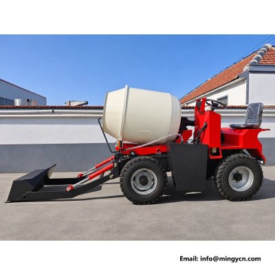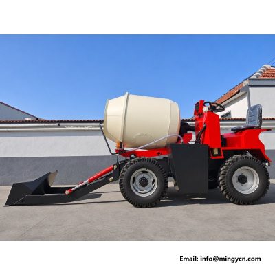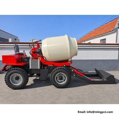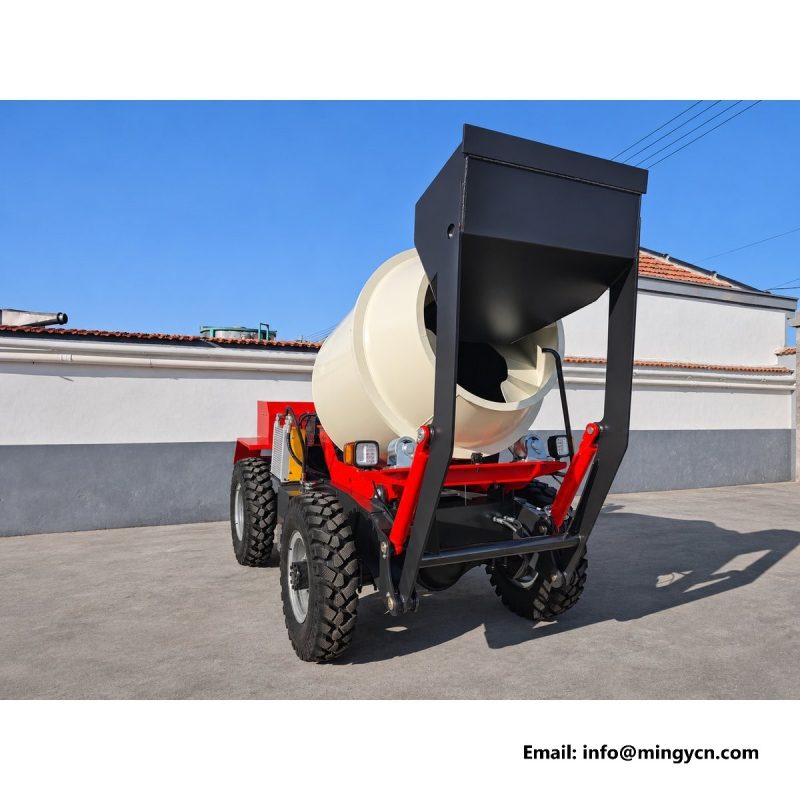
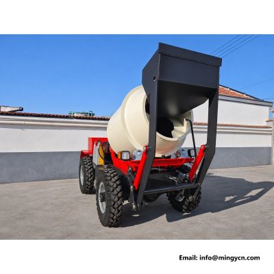
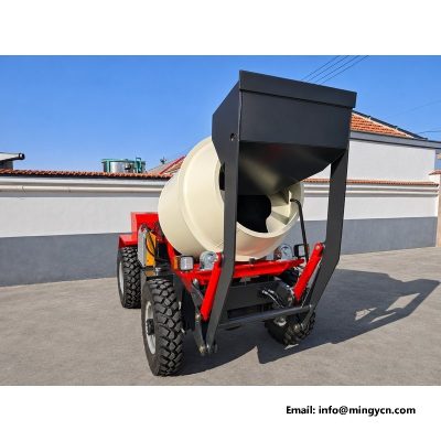
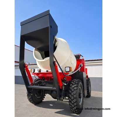
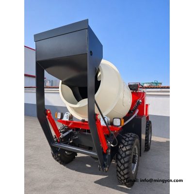
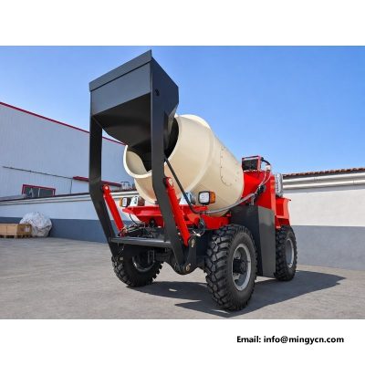
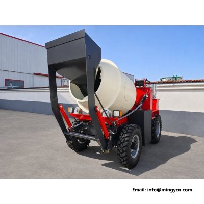
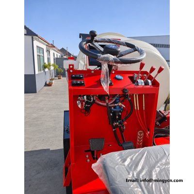
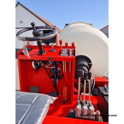
drum side and drive end: motor, gearbox and hose routing
The drive end of a self loading mixer is the side that gets photographed last and matters most. These eight frames follow the drum drive from the valve block to the shell: the hydraulic motor, the reduction gearbox, the hose runs along the frame rail, the clamps that hold them, and the service space around the assembly. The machine carries a 1,500 litre drum and works it every cycle, so everything on this side is under continuous duty. The notes below read the photographs as a service engineer would, looking for routing, access and the details that decide whether the drive end stays dry and reachable.
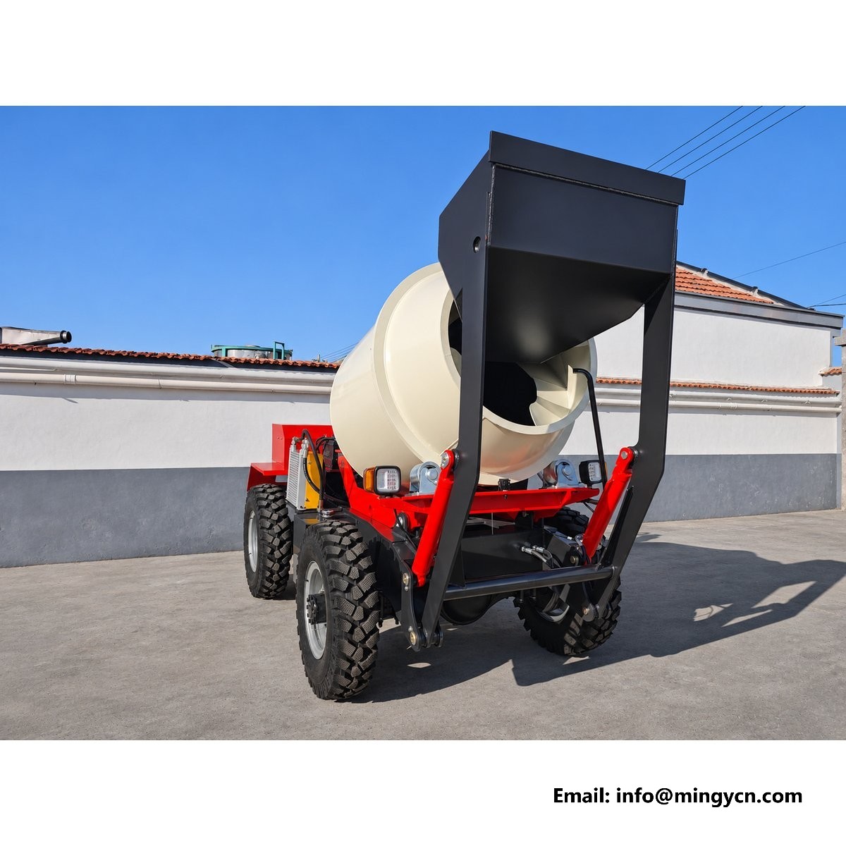
| Specification | 1.5 m³ self loading mixer |
|---|---|
| Drum capacity | 1.5 m³ (1,500 L) |
| Transmission | 4WD, 3 forward + 1 reverse + road gear |
| Engine | Single-cylinder diesel, 25 hp |
The drum does not turn by itself, and the side of the machine that makes it turn is the side buyers photograph least. These frames concentrate on the drive end: the hydraulic motor, the reduction gearbox bolted to the drum shell, and the hose runs that feed them. It is a compact arrangement, and most of it sits behind the frame rail and the drum support, which is precisely why it deserves a close look. On a self loading mixer the drum drive works every cycle, forward to mix and reverse to discharge, and it works against the full mass of a 1.5 m3 batch. Everything visible here, from the motor mount to the last hose clamp, is part of that duty.
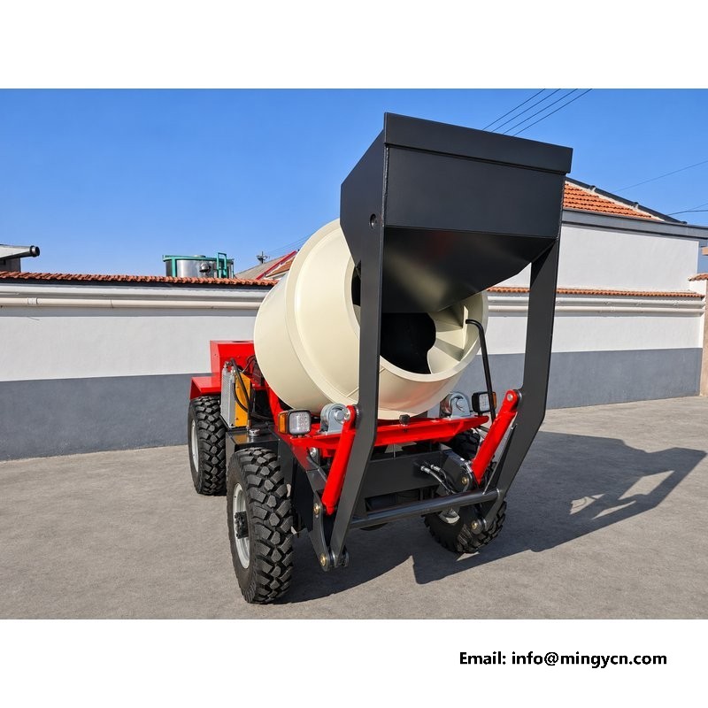
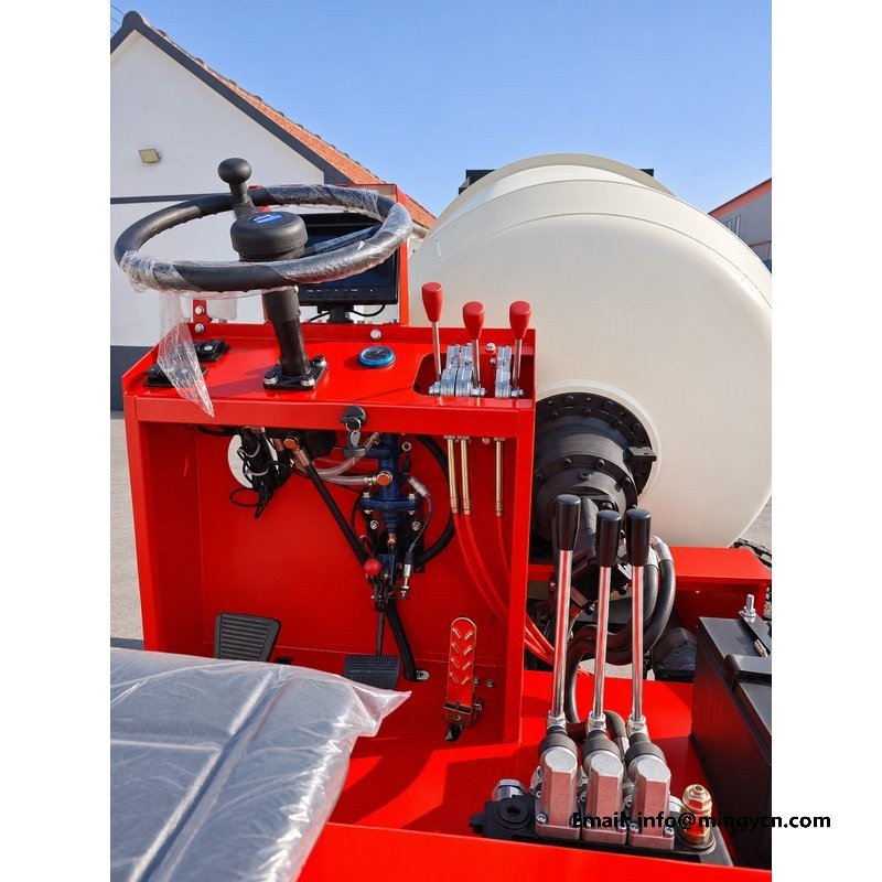
The hydraulic motor sits at the drive end of the drum, coupled to a reduction gearbox that brings the shell down to mixing speed. In the wider frames the pair reads as a single unit tucked against the drum shell, protected from the side by the frame and from above by the drum itself. That protection is worth noting. A motor mounted outboard of the frame is easy to work on and easy to knock off on a gatepost. The compromise here favours protection, which is the right choice for a site machine. Look at the mounting: the motor and reducer should sit on a machined face with a positive register, not on slotted holes that let alignment drift. Check the bolts for washers and for thread showing past the nut.
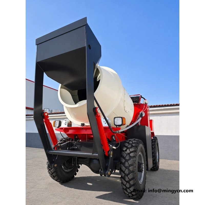
Between the motor and the drum shell there is a reduction stage, and the photographs of that joint answer a question buyers rarely ask: what happens when the drum is stopped with a full batch in it. The gearbox has to hold that mass without creeping, and the coupling has to take the shock when the operator reverses the drum to discharge. Look at the coupling guard and the shaft alignment. A protected coupling with a machined pilot keeps the shafts concentric; an exposed one collects wire, grit and binder, and runs out of alignment. The frames should also show the breather and the fill point. A gearbox that cannot be checked without removing the drum guard will be run dry, and a dry gearbox announces itself as a drum that turns slowly and then not at all.
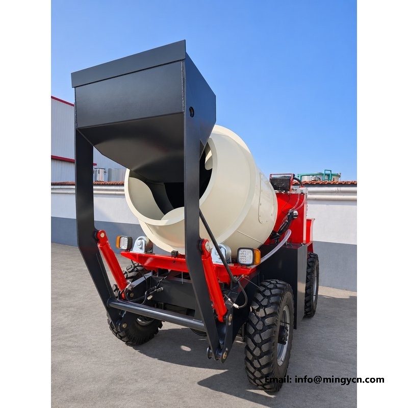
Hose routing is the clearest sign of whether a machine was laid out on a drawing board or assembled on a floor. In these frames the hoses leave the valve block, travel rearward along the frame rail, and turn up to the motor and the drum control. Every bend should be a sweeping curve rather than a fold, and every run should be supported rather than hanging. Look at the spacing between hoses. Bundled tight, they rub against each other with every pressure pulse; spread apart with clips, they stay cool and stay intact. Look also at how the lines cross the frame. A hose passing through a plate should pass through a sleeve, because a steel edge and a vibrating hose always reach an agreement at the hose's expense.
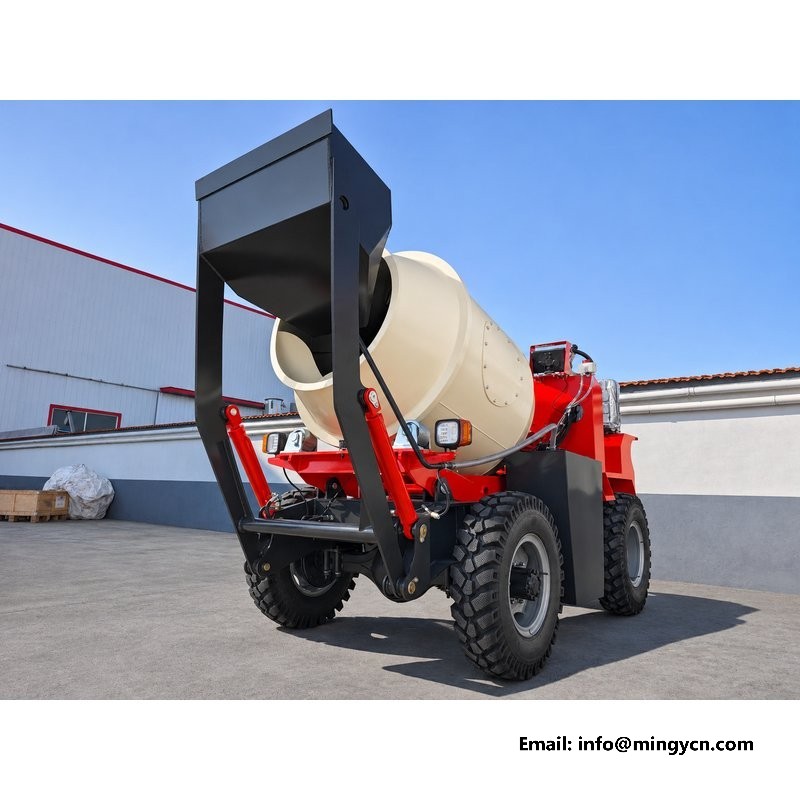
The clamps in these photographs are worth studying for their spacing, because that tells you how much thought went into the run. A hose supported at regular intervals along a rail does not move; a hose tied at the ends and left free in the middle swings with every bump and wears wherever it touches. Look for the type of clamp. A rubber-lined P-clip holds without cutting the cover, while a plain metal clip on a hydraulic hose is a slow leak waiting for its moment. Then look at the chafe points, where a line passes close to a weld, a bracket or another hose. Those are the places to examine on a machine that has been working. A clean machine in a yard proves the layout; a used one proves whether it survives.
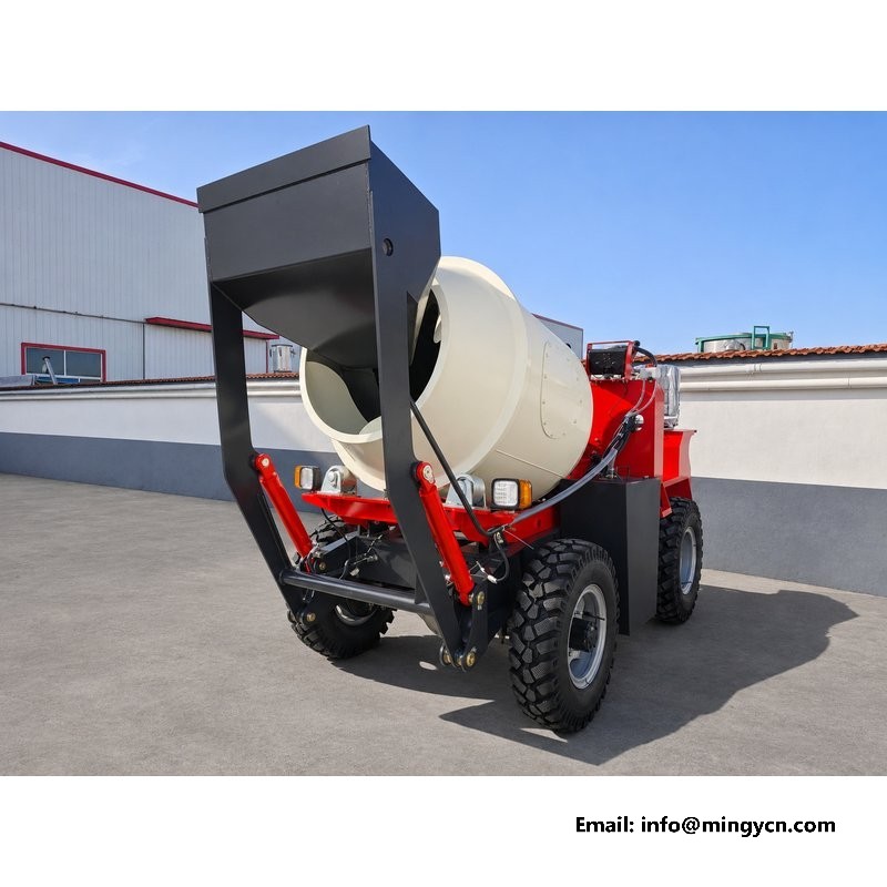
Everything on the drive end depends on clean oil, and the photographs show how the filtration is arranged. The tank, the suction line, the return filter and the breather should all be reachable from the side of the machine without lifting the drum guard or climbing onto the frame. That is a service decision made at the design stage, and it is hard to correct later. Look at the filter head position in the frames. A filter mounted high on the frame can be changed standing on the ground; one tucked under the tank requires the machine to be over a pit. Look also at the breather. One that sits low or faces upward collects dust and rainwater, and a tank that breathes dirty air puts that dirt into the oil, where it finds the motor.
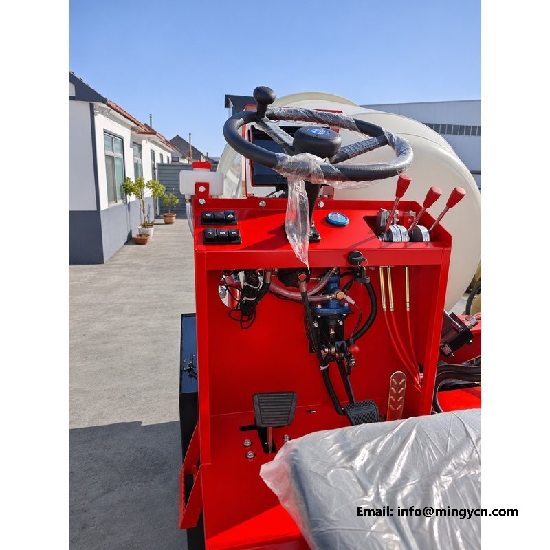
A drive end can be well built and still be a nuisance to own if nothing can be reached. These frames show the working space around the motor, the gearbox and the valve block, and a buyer should read them as a service diagram. Can a hand get to the motor mounting bolts? Is there room to swing a spanner on the hose fittings, or does the frame rail sit a hand's width away? Can the drum be barred over by hand during a check? The answers are visible in the gaps. A machine that requires the drum to be removed to change a hose is a machine that will be run with a weeping fitting for months. Good access is the difference between maintenance that happens and maintenance postponed.
The hydraulic system on this machine is fed by a single-cylinder diesel rated at 25 hp, and that pairing sets the duty cycle. A small engine driving a drum through a hydraulic transmission runs at high load for much of the shift, and the oil carries the heat away. The frames of the engine side show where the oil cooler and the fan sit relative to the pump. Look at the airflow path. A cooler mounted behind the frame with a clear exit cools far better than one tucked against a plate where hot air recirculates. Look also at the reservoir position, away from the exhaust. Hydraulic oil that runs hot loses viscosity, thin oil slips past the motor, the drum turns slowly, and the operator works the lever harder, which adds more heat.
A drive end photograph taken after a machine has run should show clean metal and dry joints, and a supplier who sends only photographs of a freshly washed machine is telling you less than one who sends both. Look at the area under the motor and the gearbox in the frames. Hydraulic oil leaves a dark film that dust sticks to, and that film is the first sign of a weeping fitting or a tired seal. Check the hose crimps for damp patches, the fittings for oil at the shoulder, and the bottom of the drum guard for drips. None of this is a defect in a photograph of a new machine, but it is the standard to hold the supplier to at handover. Ask for the same frames taken after a demonstration, before washing.
The drive end raises a short list of questions that are hard to answer from a photograph and easy to answer from a specification. Ask which hydraulic motor and which reduction ratio are fitted, and whether the drum speed is set for mixing or for discharge, because the two demands differ. Ask what protects the circuit from overpressure when the drum jams with a full batch, and where that valve is adjustable. Ask how the gearbox oil level is checked and how often it should be changed. Ask whether the hoses are rated for the working pressure with a margin, and whether replacements are a standard length. A supplier who answers these without consulting an engineer knows the machine, and that is worth more than another photograph of the paint.
Clean, dry metal around the motor and gearbox, hoses in sweeping curves with regular clips, a protected coupling, and clear access to the filter and the oil level plug. A dark film with dust stuck to it, oil at a fitting shoulder or a hose pulled tight between two points are all reasons to ask for a second set of photographs, taken after the machine has run rather than after it was washed.
Yes. A hydraulic motor drives through a reduction gearbox to the drum shell, fed by the pump on the single-cylinder engine. That arrangement lets the drum be reversed for discharge and gives the operator control over the pour without a mechanical clutch in the driveline, which also removes a wear item from the service schedule and makes the drive easier to protect from overload.
For the current specification, build options and a formal quotation for your market, contact MINGYI Machinery. E-mail: sales@mingycn.com | LINE (ID): mingyicn
Hydraulic Valve Block and Drum Drive on the 1.5m3 Self Loading Mixer · Mixing Blades and Drum Interior on the 1.5m3 Self Loading Mixer · 1.5m3 Self Loading Mixer from Every Angle: A Yard Photo Reference