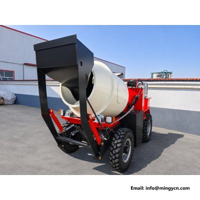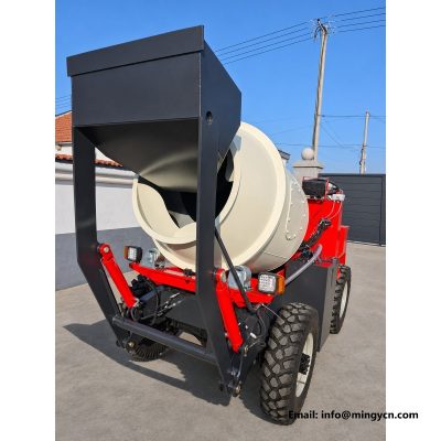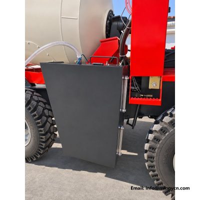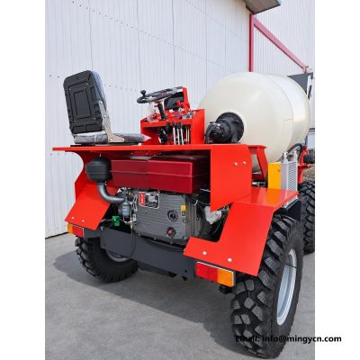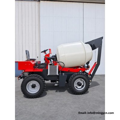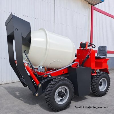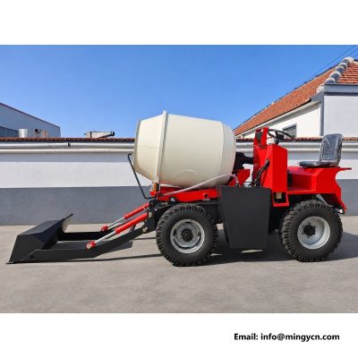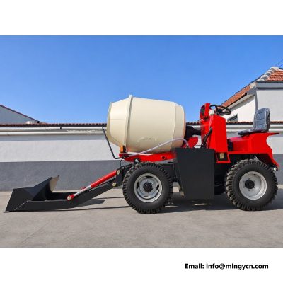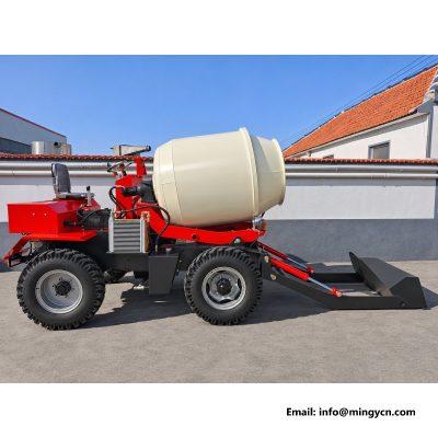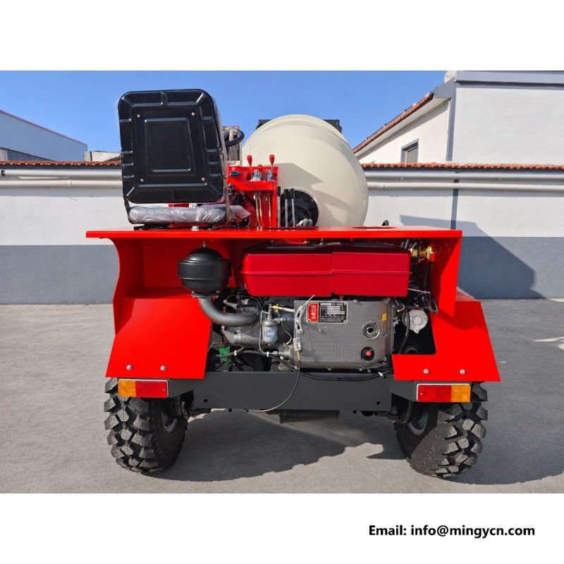
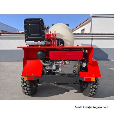
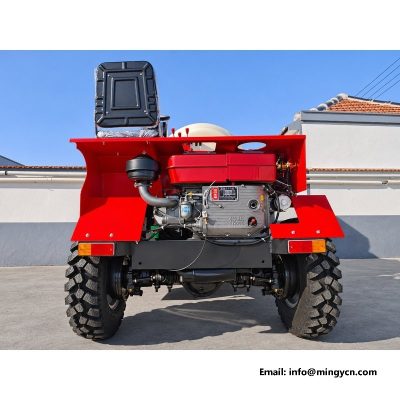
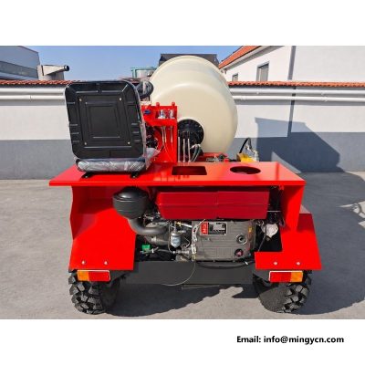
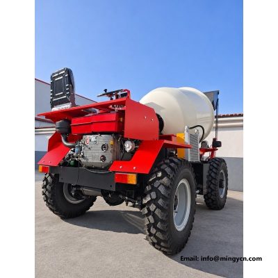
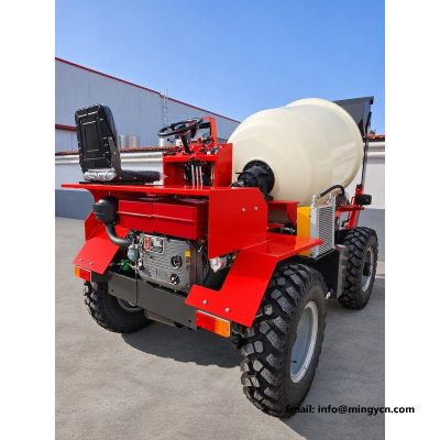
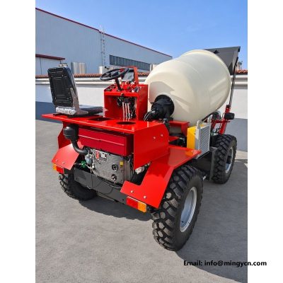
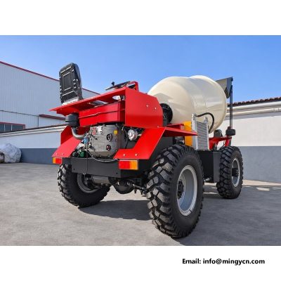
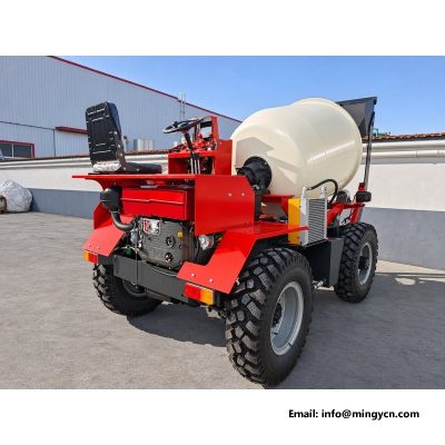
rear frame, drum mouth and discharge side from behind
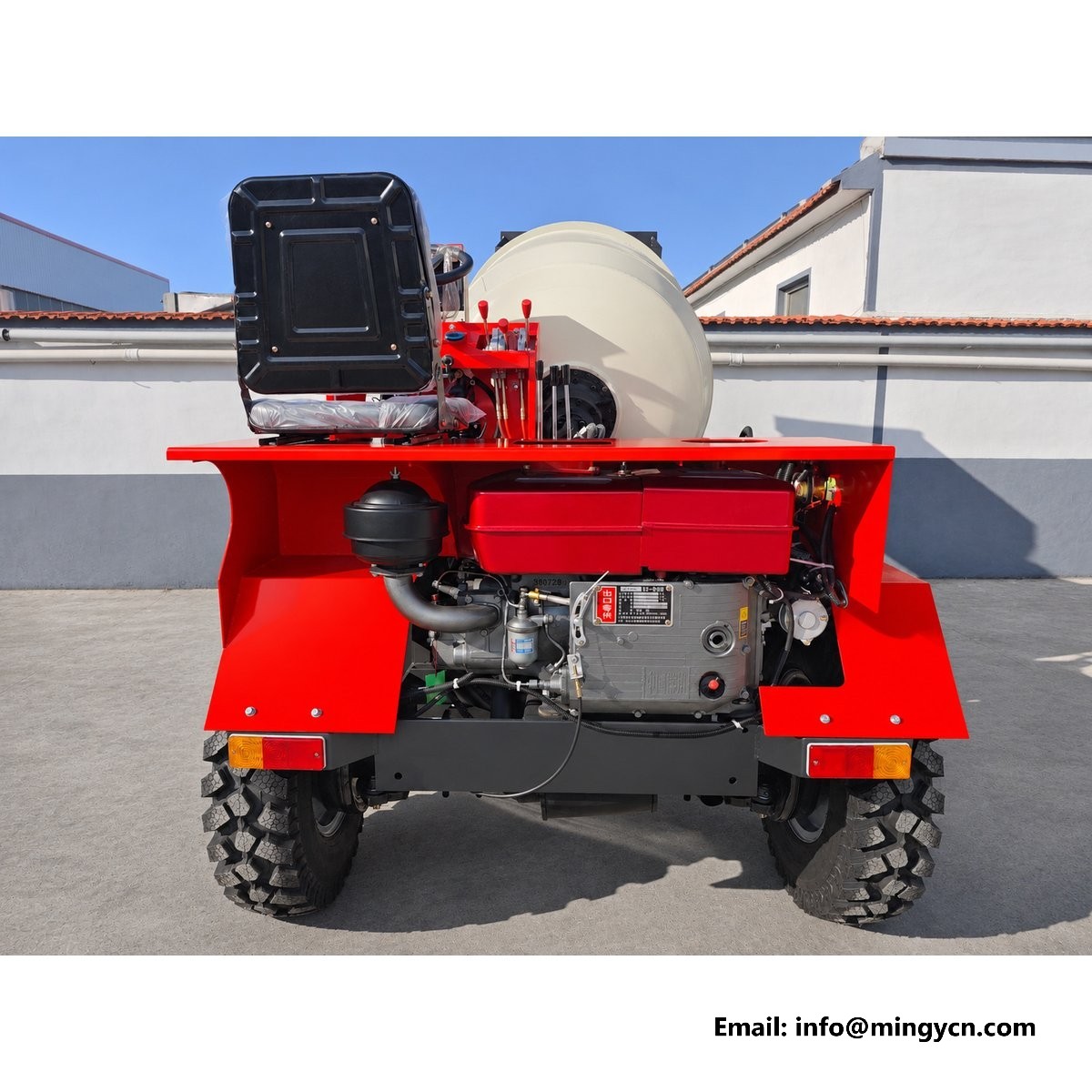
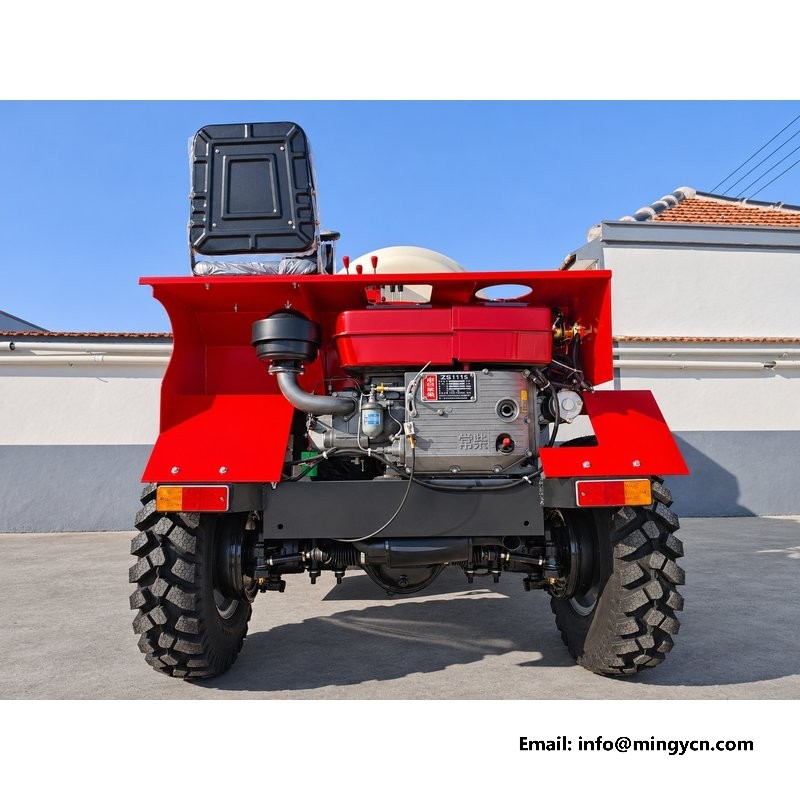
Walk around a mixer and the camera usually stops before the back. These eight frames do the opposite. They were taken from directly behind and from the rear quarters, at ground level and at eye level, and they concentrate on the parts that face the pour: the drum mouth, the chute, the rear cross member, the four-wheel-steering rear axle, the lamps and the tail of the chassis. From this side the machine shows how the mix leaves it, how it reverses, and how the frame closes at the end that carries the rear axle. The reading below follows that order without adding anything the images do not contain.
| Specification | 1.5 m³ self loading mixer |
|---|---|
| Overall dimensions (L x W x H) | 3,500 x 1,600 x 2,200 mm |
| Maximum travel speed | 24 km/h |
| Rear axle | 130 four-wheel steering |
Walk around a machine on a dealer's yard and the camera usually stops at the front three-quarter. The back gets one frame, if that. Yet the rear of a self loading mixer is where the product actually leaves the machine, and it is where a buyer can learn how the discharge was designed. These photographs are all taken from behind or from the rear quarter: the drum mouth, the chute, the rear frame, the axle and the tail of the chassis. Nothing here is decorative. Every element in these frames has a job during the pour, and each one is loaded, hot, or in the way of the operator at some point in the cycle, and most of them are judged badly from the front.
The drum mouth is the opening at the rear of the shell, and the photographs show its size relative to the drum and the way the chute is formed. A wide mouth discharges a wet mix quickly, which matters when the batch is stiff or the site is short of time; a narrow mouth gives more control but slows the pour. What the frames should show is the lip. A rolled or reinforced lip holds its shape when the mix is scraped out; a thin edge deforms, and then the chute no longer seats against the drum. Look at the transition between the shell and the mouth. That weld works hardest, taking the rotation and the weight of the mix pressing outward at the same time.
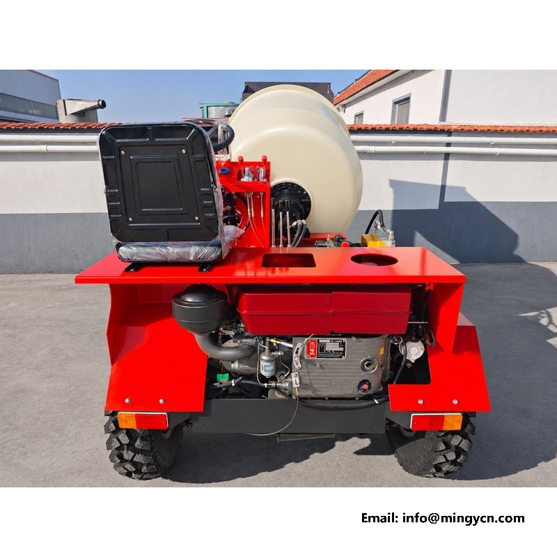
Discharge height is the measurement that decides how the machine is used on site. In these rear frames the mouth sits above the chassis rail, and the gap below it is where a barrow, a bucket or a small dumper is placed. That gap needs to clear a loaded barrow without the operator tipping the mix from a height that separates the aggregate. Look at the frames taken square to the rear: the vertical distance from the mouth lip to the ground line is the working height, and it should read as comfortable rather than generous. A high mouth means a long drop and a mix that lands in a heap; a low mouth means the barrow has to be pushed under the drum. A chute extension changes the reach.
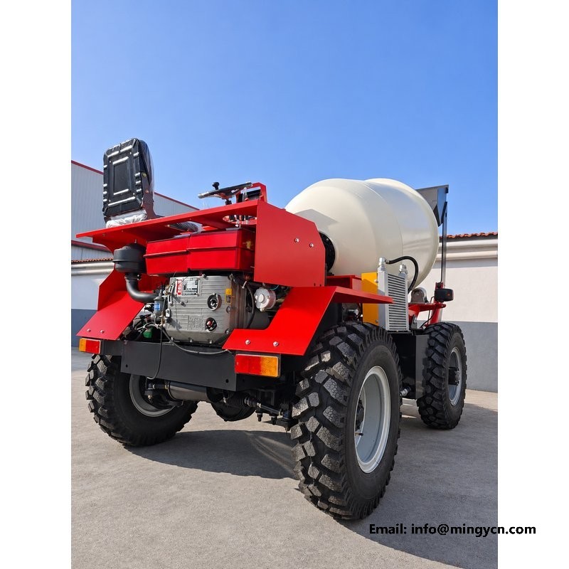
Behind the drum the chassis closes with a cross member, and the photographs show how that end of the frame is tied together. It is the point where the rear axle loads, the drum support and the discharge forces all meet, and it is usually the last place a manufacturer adds steel because it is the least visible. Look at the depth of the section and whether the cross member is a formed plate or a plain flat bar. A formed section resists the twisting that comes from a rear axle working on uneven ground; a flat bar flexes and eventually cracks at the weld toes. Look also at how the drum support is attached at this end, and whether the bracket spans the full width.
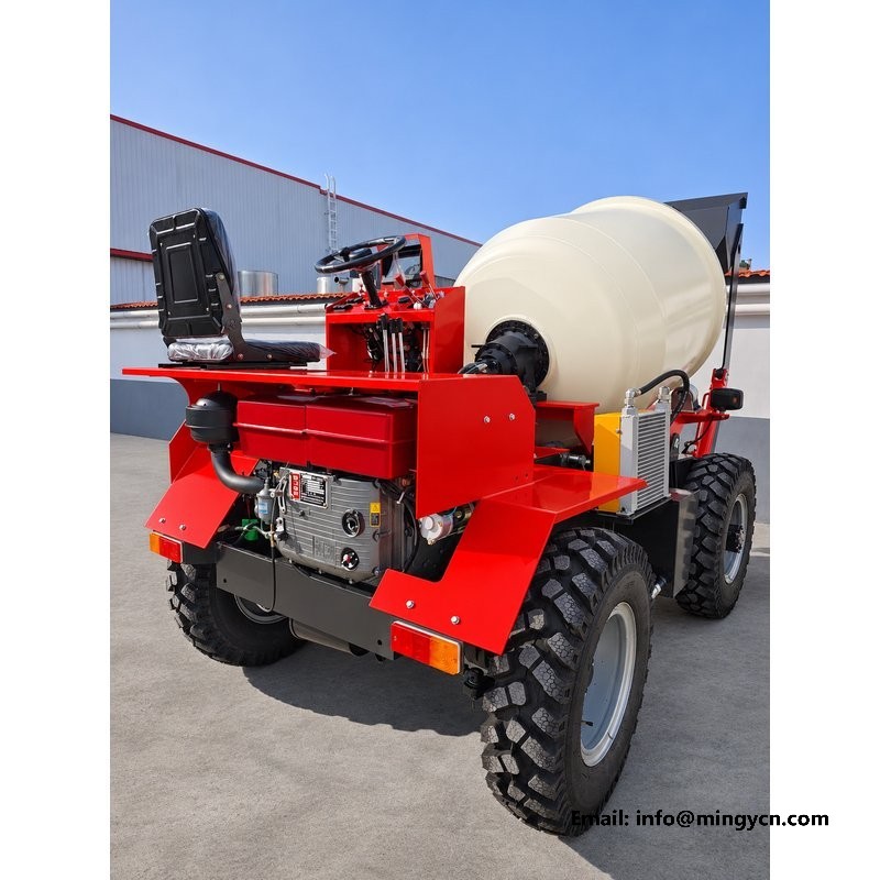
The rear axle on this machine is a four-wheel-steering unit, and the rear frames are the only place its linkage can be studied. Look at the steering arms, the tie rod and the ram, and how they sit relative to the frame and the drum above. The linkage has to work through the same 28 degrees as the front without the rod interfering with the chassis or the hose runs. In the photographs, check that the rod ends are protected and that the ram is mounted above the axle tube rather than below it. A ram hanging under the axle in a yard with kerbs and rubble will be replaced early. The track rod adjustment should be accessible with the machine on the ground, not jacked up.
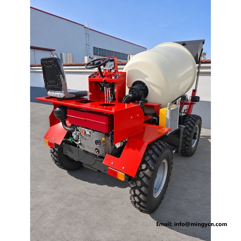
The value of four-wheel steering shows up in a turning circle of 2,464 mm, and in a yard that figure is what lets the machine work between a wall and a stack of blocks. The rear frames tell you something a brochure cannot: whether the rear wheels actually turn, and how far. Look for a photograph with the steering at full lock, taken from behind. The rear wheels should be visibly angled against the frame, and the linkage should be clear of its stops. Then think about reversing. A mixer spends a good part of its day backing up to the pour point, and the operator's view over the drum is limited. A compact rear free of projections is easier to place.
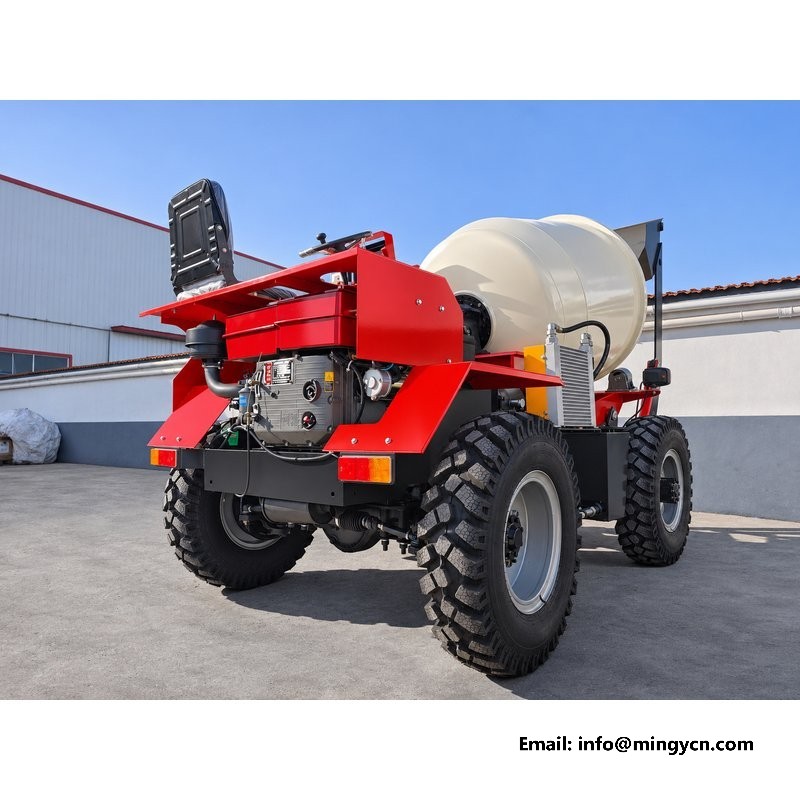
The rear of a machine is where the road-legal details live, and their placement says something about whether the manufacturer thought about transport. The lamp clusters, the plate holder and the reflectors should sit where they are protected by the frame rather than hanging off the drum guard. In the photographs, look at how the lamps are mounted. A lamp on a short bracket bolted to a plate can be replaced in a minute; a lamp recessed into a moulded panel is neater and harder to service. Check the wiring route from the lamps into the frame. It should pass through a grommet and run inside the rail, not along the outside where a branch or a gatepost can hook it.
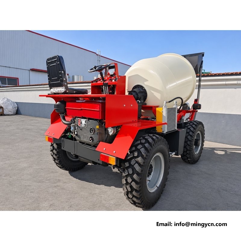
Sit in the seat and look back and the drum fills the view, which is why the rear photographs matter. From behind, the camera sees what the operator cannot: the blind area directly behind the chassis, the height of the drum mouth relative to a person standing at the pour point, and the space the machine needs to swing its chute. In the frames here the drum sits high and the view under it is open, which is the arrangement you want for reversing into a tight spot. Look at the width of the rear frame against the tyre track. A frame narrower than the track leaves the tyres as the widest point, and the tyres are what an operator judges distance by when backing up.
The rear of the chassis is where the hydraulic lines from the drum circuit and the lighting harness end up, and it is the most exposed part of the machine. The frames show the hoses turning down and forward into the frame, and the key detail is whether they are protected along that last stretch. Look for a sleeve, a spiral wrap or a steel guard over anything that runs behind the rear axle. Look also at the lowest point of the hose run. A hose that hangs below the axle tube will be the first thing to meet a kerb, and a hydraulic hose pinched between a kerb and a frame is a burst, not a leak. The tail should read as a closed, tidy assembly.
Rear photographs prove three things the front of a machine cannot. They show the discharge arrangement, so you can judge how the mix will leave the drum and how a barrow will fit under it. They show the rear axle and its steering linkage, so you can see whether four-wheel steering is properly engineered or simply added. And they show how the chassis terminates, which is where a frame either closes properly or is left open and vulnerable. Take the views together, square on, rear quarter and low, and compare them with the figures you already have: 3,500 mm long, 1,600 mm wide, 2,200 mm high. If the proportions in the photographs match those figures, the images are honest and the machine is what the specification describes.
It shows the discharge arrangement, the height of the drum mouth above the ground, and how much room a barrow has underneath. It also shows the rear axle and its steering linkage, and how the chassis closes at the tail, which is where a frame is most often left open. That is also where the reversing blind area begins. None of it appears in a front three-quarter shot.
The rear axle steers as well as the front, which brings the turning circle down to 2,464 mm. In a yard with walls or stacked blocks, that lets the machine turn around where a two-wheel-steer unit of the same length would need a three-point manoeuvre. It also shortens the time spent repositioning at the pour point, which is where a mixer loses most of its working day.
For the current specification, build options and a formal quotation for your market, contact MINGYI Machinery. E-mail: sales@mingycn.com | LINE (ID): mingyicn
Drum Mouth, Discharge and Pour Control on the 1.5m3 Self Loading Mixer · Welded Chassis Frame on the 1.5m3 Self Loading Mixer · 1.5m3 Self Loading Mixer from Every Angle: A Yard Photo Reference