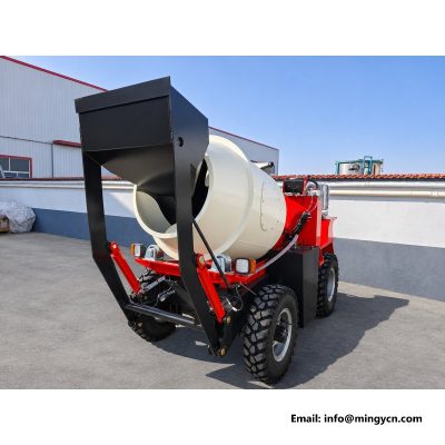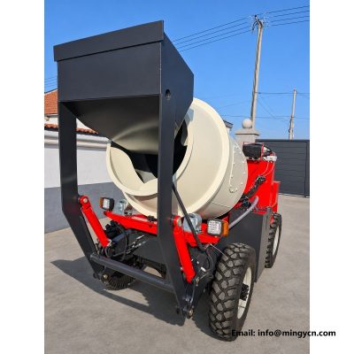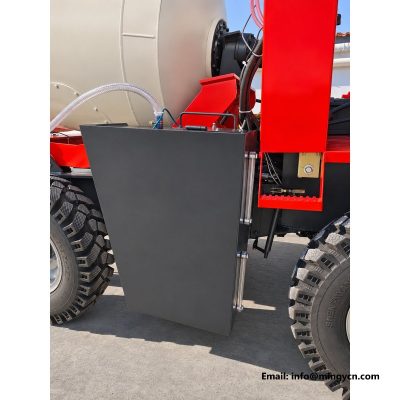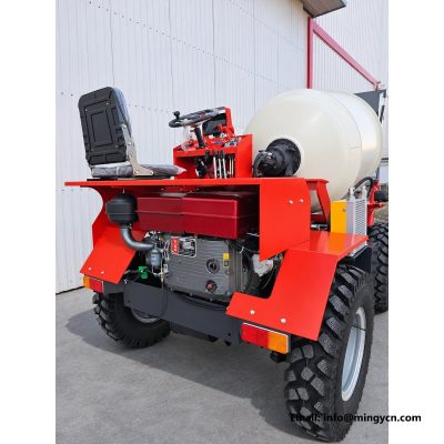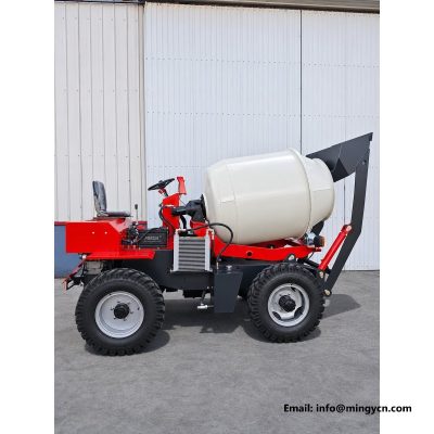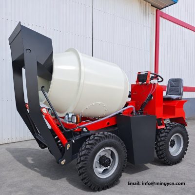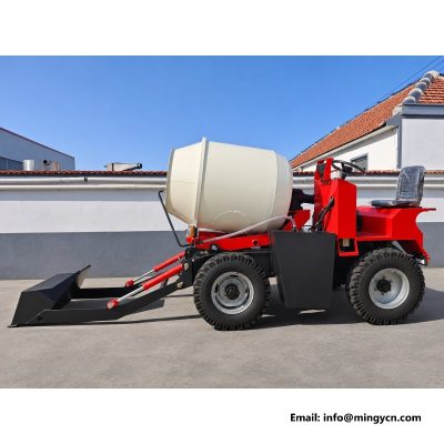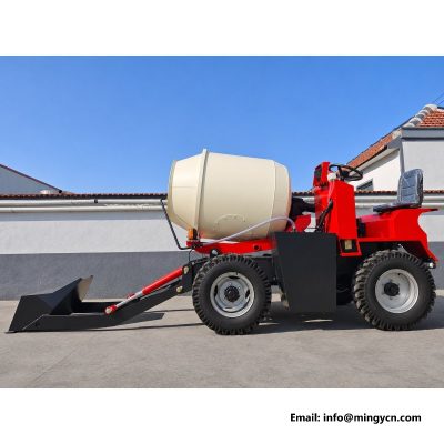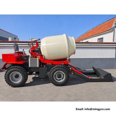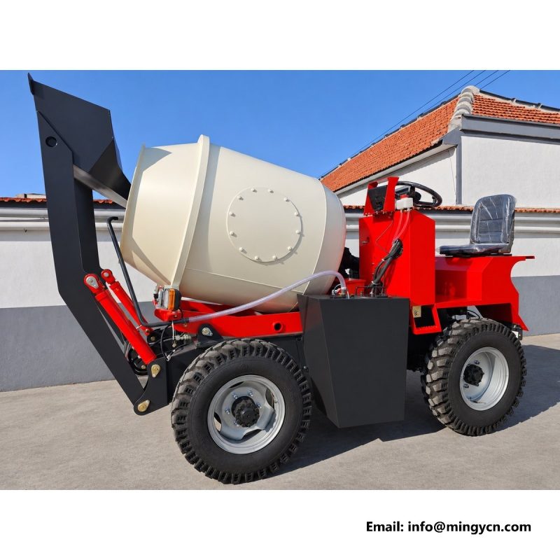
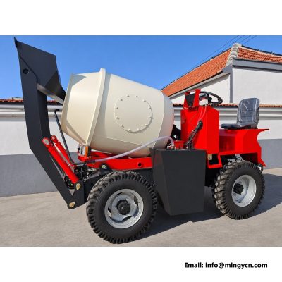
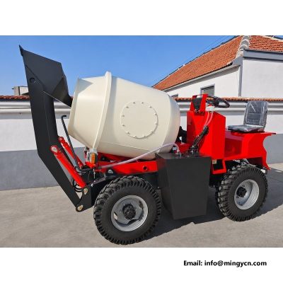
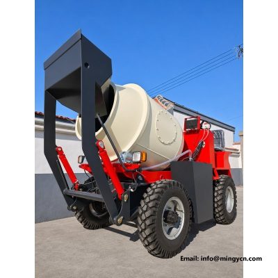
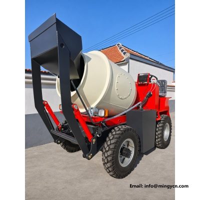
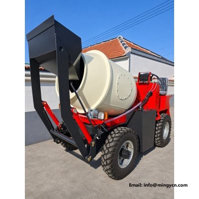
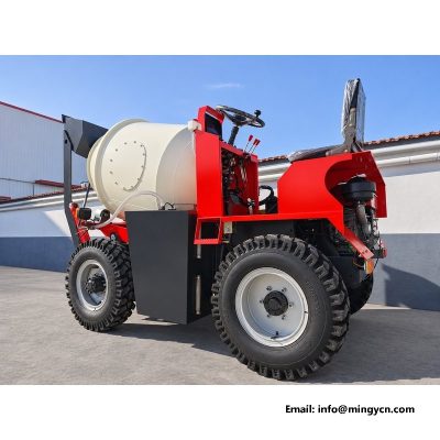
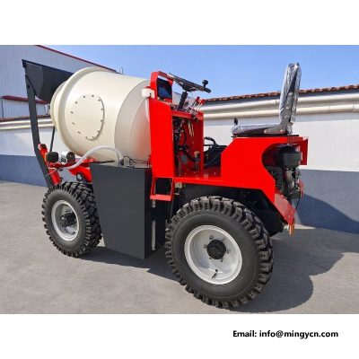
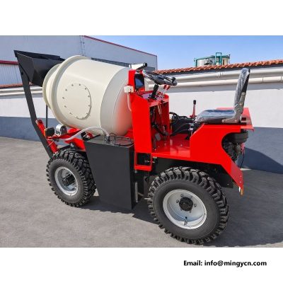
left side in the yard: frame welds and bracket alignment
The left flank of this machine carries less plumbing than the right, which makes it the better side for reading structure. These eight frames were taken in the same yard and from the same distance as the right side views, so the two sets can be compared directly. What they show is the frame from the front cross member to the tail, the bracket stations along the rail, the front axle mounting and the clipped runs that follow the structure. The commentary below works front to rear, then compares left with right, because symmetry is the quickest test of how a chassis was assembled.
| Specification | 1.5 m³ self loading mixer |
|---|---|
| Operating weight | 1,900 kg |
| Overall dimensions (L x W x H) | 3,500 x 1,600 x 2,200 mm |
| Minimum ground clearance | 204 mm |
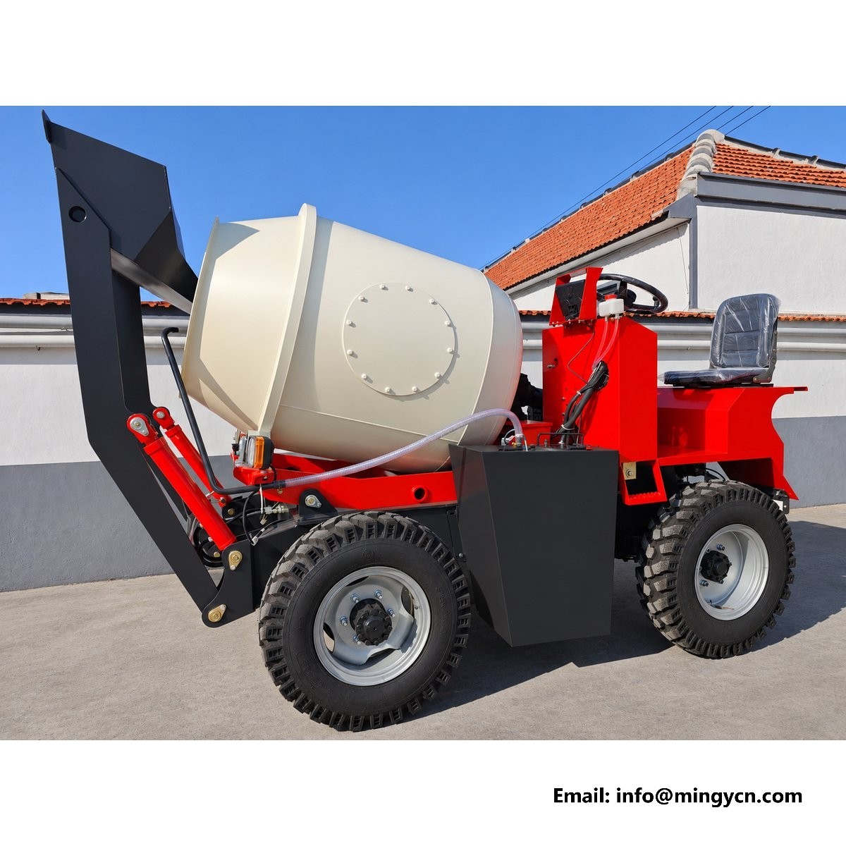
The left side of a self loading mixer carries less plumbing than the right and shows more structure, which is why it is the better side for judging how the machine is built. These photographs were taken in the same yard, against the same wall, at the same distance as the right side frames, and that makes them directly comparable. What the left flank records is the frame from the front cross member to the rear cross member, the axle mounts, the welds along the rail, the brackets that carry the tank and the guards, and the way the driveline is routed forward. Nothing here is hidden by a hose bundle. Read this side for structure first and finish second.
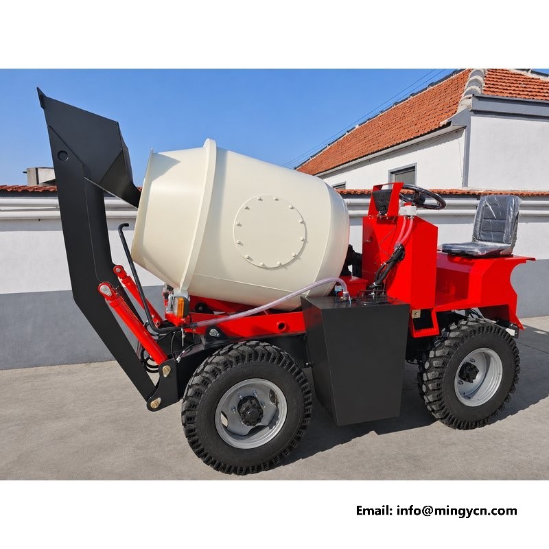
Follow the main rail from the front of the machine to the rear in these frames and the weld pattern becomes clear. The rail is a fabricated section, and the longitudinal seams run the full length with brackets welded across them at each mounting station. Look at the consistency of the bead as it passes a bracket. A welder who slows at the bracket and then resumes leaves a lump; a welder who runs through leaves a continuous bead that ties the bracket into the rail. Both hold, but the continuous run distributes stress far better at the toe. Look at the underside of the rail as well, where the frames catch the shadow, and see whether the weld is complete there too.
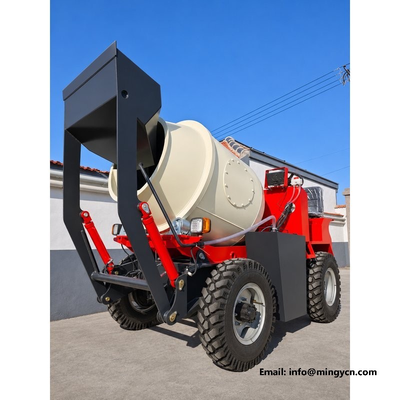
Brackets are where a frame either works or fails, and the left side shows them clearly. In these frames the brackets for the tank, the guards and the drum support sit at intervals along the rail, and their alignment can be judged against each other. The bolt holes should line up on a common centre line, and the bracket faces should sit square to the rail rather than tilted. A bracket welded on at an angle forces its bolt to carry a bending load, and a bolt in bending loosens. Look also at how each bracket meets the rail. A bracket with a gusset spreads its load along the rail; one welded straight onto a flat face concentrates everything at a single toe.
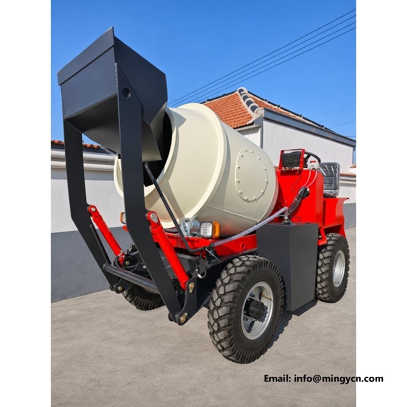
The front axle on this machine is an Isuzu-type reinforced unit, and the left side frames show how it is hung under the frame. Look at the mounting: the axle should sit on a saddle or a pair of hangers that distribute the load into the rail, with the clamp plates visible and evenly tightened. Look at the mounting arrangement and how much space it leaves for axle movement. A rigid mount transmits every shock into the frame; one with some compliance keeps the tyres on the ground. Also look at the steering components on this side. The drag link and the steering arm should be clear of the tyre through the full 28 degree sweep, and no hose should be routed where the axle can trap it.
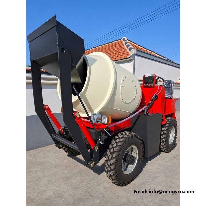
Even on the structural side there are lines to manage, and the left rail in these frames carries the harness and a set of hoses running forward to the axle and the lights. What matters is the fixing. Look for a regular spacing of clips, a consistent stand-off from the rail, and a protective sleeve wherever a line passes a weld or a bracket edge. A harness cable-tied to a hose pulls on it every time the frame flexes; a harness on its own clips moves independently and lasts. Look also at the lowest point of each run. Anything that dips below the rail collects water and grit, and a connector sitting at that low point corrodes from the inside.
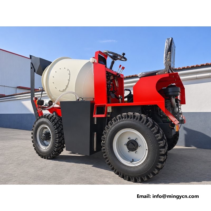
Symmetry is the fastest quality check available to a buyer with photographs of both sides. Put the two views side by side and compare the height of the frame rail from the ground, the position of the axle centre, the angle of the front and rear cross members and the placement of the brackets. On a machine built on a jig, these read as mirror images. On a machine assembled freehand, one side sits lower, one bracket is further forward, and the drum does not sit square in the frame. None of these differences is obvious in a single photograph; all of them are obvious in a pair. That is why these frames were taken from the same spot on both sides. Take that comparison before you look at anything else on the machine.
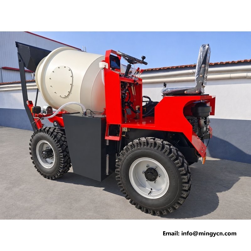
Structural joints on a chassis are usually welded, but the parts that wear or need replacement are bolted, and the left side shows several of them. Look at the bolt heads along the rail and at the axle clamp. A joint that has been torqued correctly often carries a paint mark across the head and the plate, applied after tightening so that any movement shows as a broken line. That mark is a small thing, but its presence tells you the assembly had a torque procedure and a check. Look also at the length of thread past each nut: enough to show full engagement, not so much that it becomes a hook for wire and clothing. The grade markings on the heads should match across joints of the same duty.
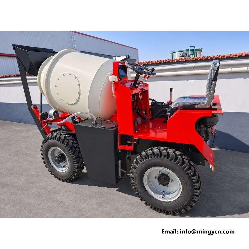
A painted frame is a sealed frame, and the sealing is what protects it, but paint also covers the evidence. On the left side frames the welds read as soft ridges under the finish, and that is enough to judge their line but not their profile. What a buyer can still assess is the preparation. Look for sharp edges that have been broken before painting, for a consistent coating on the inside of the rail where it can be seen, and for any area where the paint has run or sagged. Runs mean the coat was applied too heavily in one pass; dry patches mean the surface was not prepared. Both point to a finishing line working to speed rather than specification.
The operating weight of this machine is 1,900 kg, and the left side view is the best place to judge how that mass is distributed. The engine sits toward the front, the drum over the middle, and the rear axle carries the tail. In the frames, look at the position of the front axle relative to the bucket and the position of the rear axle relative to the drum. A machine with the rear axle set well back has a long wheelbase and a steady ride; one with the axle forward turns tighter but pitches more. Look at the tyre sidewalls at both ends in a side view: the deflection shows where the weight stands when the machine is empty.
Use the left side frames as a checklist and the inspection becomes a sequence rather than a hunt. Start at the front cross member and follow the rail rearward: weld continuity, bracket alignment, hose clipping, axle mounting, tail closure. Then compare each item with the same item on the right side. Then step back and look at the machine as a whole: does it sit level, are the tyres equally loaded, does the drum sit square between the rails? A machine that passes those checks in photographs is worth travelling to see. A machine that fails one of them in a photograph will not improve in person. The purpose of these images is to arrive at the inspection knowing where to look.
Compare the two sides. Rail height from the ground, axle position, bracket spacing and cross member angle should read as mirror images. Differences that are invisible in a single frame stand out in a pair, and they are the first sign that a chassis was assembled without a jig, or that a bracket was replaced after damage and set by eye. Take that comparison before anything else.
The left flank carries fewer hoses, so the frame rail, the bracket stations and the axle mounting are less obscured. On this machine the right side is busier with hydraulic runs, which is useful for judging routing and protection but less useful for judging the structure underneath, where weld continuity and bracket alignment decide how the chassis behaves over years of loaded work.
For the current specification, build options and a formal quotation for your market, contact MINGYI Machinery. E-mail: sales@mingycn.com | LINE (ID): mingyicn
Welded Chassis Frame on the 1.5m3 Self Loading Mixer · 1.5 m3 Self Loading Concrete Mixer: Full Specification and Walkaround · 1.5m3 Self Loading Mixer from Every Angle: A Yard Photo Reference