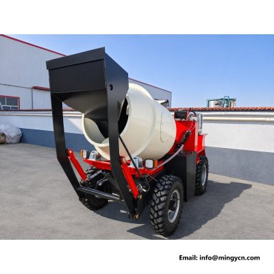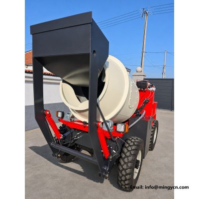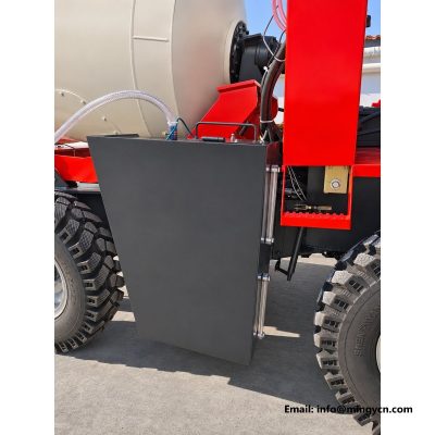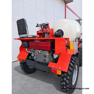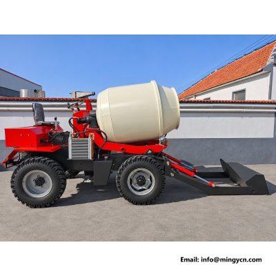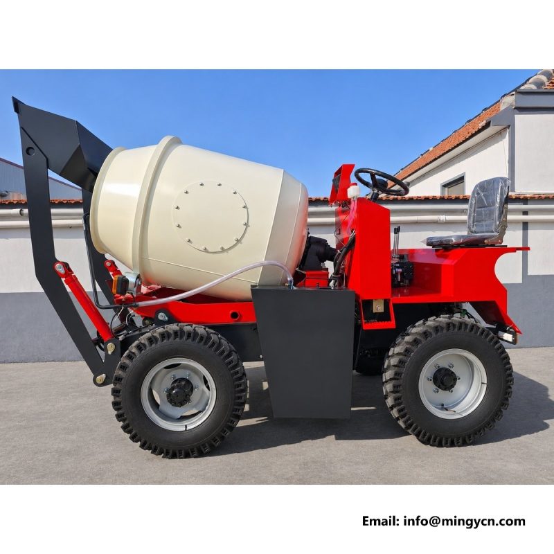
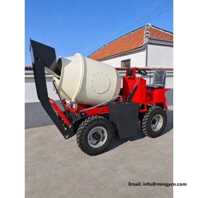
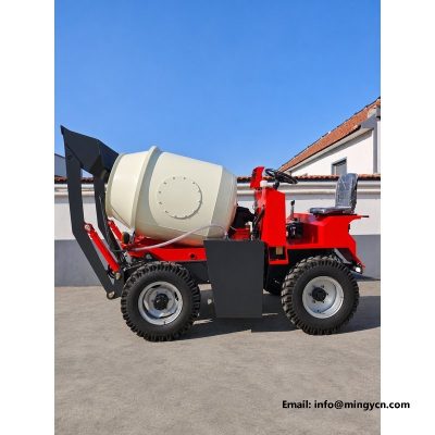
drum and lift arm: clearance and pivot points
Clearance is the quiet specification. It does not appear on a data sheet, it cannot be read from a catalogue, and it decides whether a machine works smoothly for years or starts rubbing something in its first season. The eight frames on this page put the drum and the lift arm in the same view, at rest and part way through the arc, so the gaps between them can be read directly. Work from the ground up: tyre, frame, pivot, arm, shell. Every distance in that chain is a load path, and every one of them has to survive a full bucket rather than an empty one.
| Specification | 1.5 m³ self loading mixer |
|---|---|
| Rated load | 5,000 kg |
| Drum capacity | 1.5 m³ (1,500 L) |
| Overall dimensions (L x W x H) | 3,500 x 1,600 x 2,200 mm |
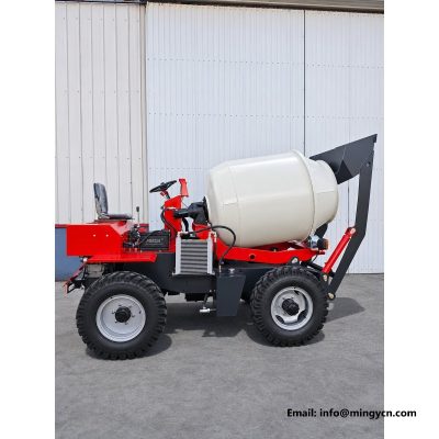
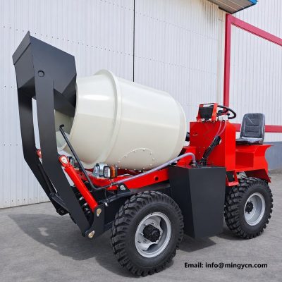
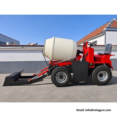
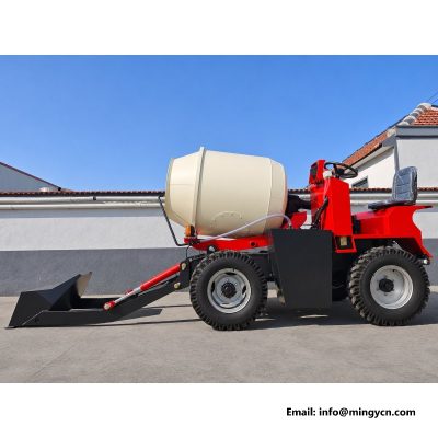
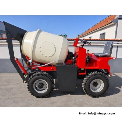
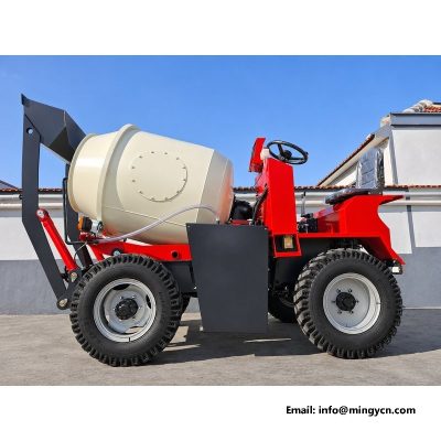
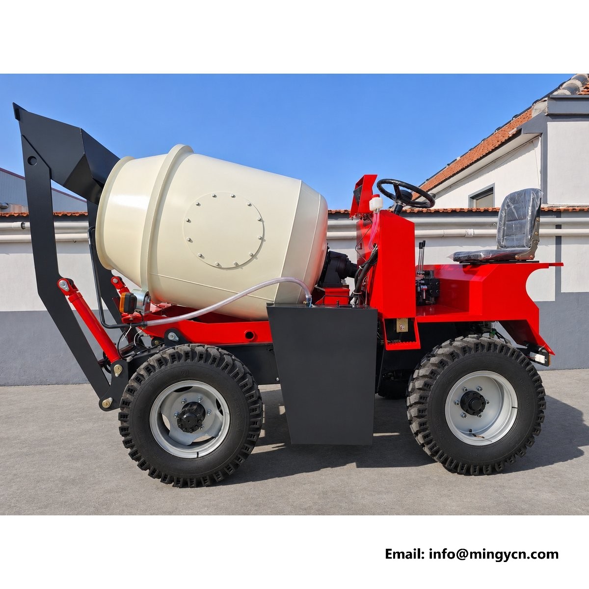
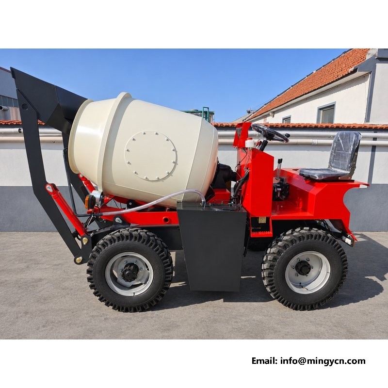
The side view is the frame of reference for everything else on this page, because it is the only angle where the arm, the pivot and the drum share one plane. Start at the tyre contact patch and work upward: the 750-16 tyre, the rail behind it, the pivot boss, the arm rising forward, and the drum shell sitting behind the arm. Each of those is a load path, and the distances between them are what the photographs are really measuring. Read the machine this way and attention moves away from paint and onto whether there is room for the arm to work. That shift is the purpose of the set. A machine that looks crowded in a side view will behave like a crowded machine in a yard.
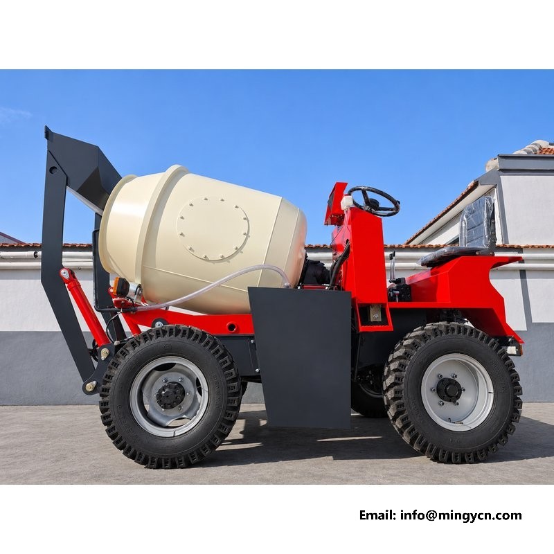
At rest the arm lies along the frame and the gap to the drum shell is at its widest, which makes this the easiest frame for judging whether the two were designed together or merely assembled. Look at the space between the inner face of the arm and the nearest point of the shell. It should be even along the length of the arm, not tapering towards the pivot. An even gap means the arm and the drum share a common centre line. A gap that closes at one end usually means a mounting plate has been set slightly out of position, and that error grows into contact once the arm rises and the frame twists under a full bucket.
The pivot is the point where an arm load becomes a frame load, and its height above the rail explains a good deal about how the machine feels when the bucket is full. Set low, the pivot keeps the arm short and the lift cylinder well loaded. Set high, it shortens the arc but raises the push point into the drum envelope. In these frames the boss is welded across the full depth of the front frame rather than onto the outer face alone, so the pull is shared by both rail faces. That detail is worth zooming into. A boss attached to one plate only will eventually crack at the toe, on the side nobody photographs. Measure that depth with a rule rather than by eye, and photograph the result beside the boss.
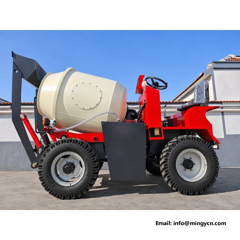
Every hinge on the machine is a wear item, and the arm pivot wears fastest because it moves under load rather than free. What the close frames show is the joint architecture: a pin passing through a machined bush, retained at one end, with a grease path drilled to the load zone rather than to the outside of the boss. Retention matters as much as material. A pin held by a single bolt and a tab washer can walk if the tab is not folded, and a pin that walks will machine its own clearance into the boss faster than any grease can compensate. Look for a positive stop, not just a fastener. Ask whether the bush is a press fit or a split type, because that decides whether a field repair needs a press.
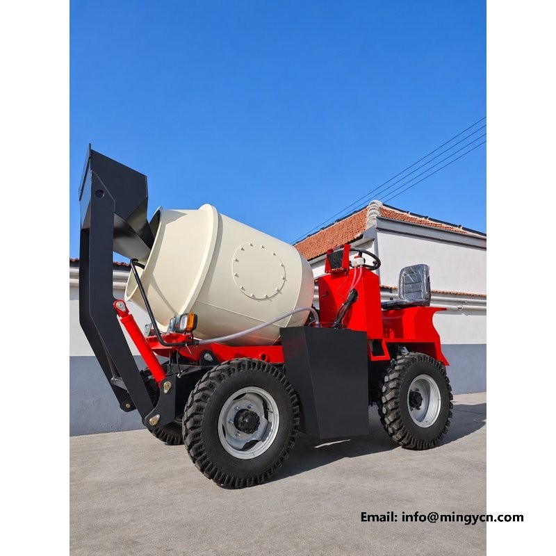
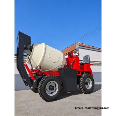
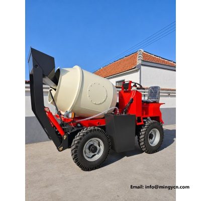
Interference is not a hypothetical. It is what happens when a hose, a bracket or a weld tab occupies space the arm needs as it rises. The way to check is to sweep the arm slowly through its arc with the machine stationary and watch the zones that matter: the inner face of the arm against the drum saddle, the cylinder rod against the frame nose, and the hose bundle against the top edge of the shell. In the frames here the arm is caught at part lift, which is where most contact occurs, because the geometry is tightest before the arm swings out and over. Ask for rest, mid-travel and full lift rather than one flattering angle. A slow sweep tells you more than a fast one, because contact shows as a change in sound before it shows as a mark.
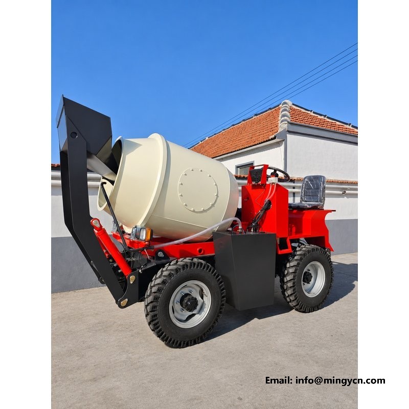
The grease points are small, easy to photograph badly, and the best single indicator of how a machine has been kept. On this assembly the nipples sit on the boss ends and on the cylinder eyes, angled so a coupler can reach them without the operator lying on the ground. Two things to look for in a photograph: whether the nipples are recessed where a stone cannot shear them, and whether there is a ring of old grease around each one. A dry nipple on a machine with hours on it is not a cosmetic issue. It means the joint has been running metal on metal since it left the yard. Count the points and compare that number with the maintenance chart; a joint with no nipple at all has to be dismantled to be lubricated.
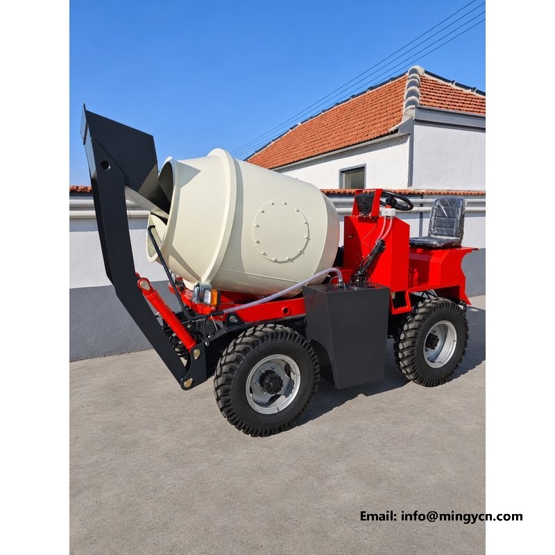
An arm is a beam, and beams bend. The useful question is not whether it flexes but whether it returns. In a side view, sight along the top edge of the arm and compare it with the frame line below: the two should read as a constant relationship along the whole length. A gentle taper built in at the factory is normal. What is not normal is a kink near the pivot or a ripple in the plate face, both of which suggest the arm has been asked to carry more than it was designed for. Photographs taken square to the flank, not from three quarters, are the only ones that show this honestly. Look at the paint near the pivot for fine cracks radiating from a weld, which is the earliest visible sign of overload.
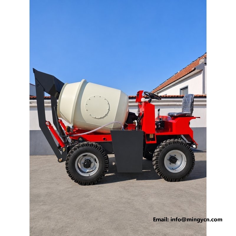
The hydraulic lines along the arm take more punishment than any other hose on the machine, because they flex every time the bucket moves and they sit in the path of whatever the tyres throw up. Good routing has three habits: the hose leaves the frame through a fixed clamp, runs with slack along the arm, and arrives at the cylinder with a gentle bend rather than a fold. In these frames the bundle is held off the plate by spacers, which keeps the cover from rubbing on a weld seam. Look for abrasion marks near the clamps. A shiny patch is the start of a failure that will happen at the worst moment. Ask what happens to the bundle at full height: it should straighten, not pull taut against the last clamp.
At the top of the arc the relationship reverses: the arm is high and the drum is below it, and the clearance that mattered at rest is no longer the one that matters. What to watch here is the space between the upper edge of the arm and the drum bands, and between the bucket heel and the mouth rim. Both are tight by design, because a machine that carried the arm further forward would need a longer frame and a heavier counterweight. In the frames where the arm is raised, the band clamps should still be visible and unobstructed. If a clamp disappears behind the arm, service access has been traded away for reach. Photograph the gap with the arm raised and the drum empty, then repeat with a full drum if the machine is available.
When the machine arrives, repeat these frames yourself before signing anything. A small set covers most of it: a square side view with the arm down, the same view at half lift, a close frame of the pivot with a rule held against the gap, and one of the grease points after the first greasing. Take them in the same order each time and keep them. A set like that does two jobs. It establishes a baseline for wear, and it settles any later argument about condition. Suppliers respond differently to a buyer who photographs the pivot than to one who only photographs the drum. Keep the set with the delivery paperwork, note the date on the back of each frame, and repeat the same views at the first service interval.
The gap between the inner face of the lift arm and the drum shell, with the arm down. It should be even along the arm rather than tapering towards the pivot, because an even gap means the two assemblies share a centre line. Then repeat the check at half lift, where the geometry is tightest. If you can only take one photograph, take that one.
Look for a bright wear ring around the pin head, a displaced tab washer, or a polished patch on the boss face where the pin has walked. Grease around the joint should be old and settled, not fresh over bare metal. On a machine with hours on it, a completely dry nipple at the arm pivot is the strongest signal that the joint has been neglected.
For the current specification, build options and a formal quotation for your market, contact MINGYI Machinery. E-mail: sales@mingycn.com | LINE (ID): mingyicn
Loading Hopper and Lift Arm on the 1.5m3 Self Loading Mixer · Mixing Blades and Drum Interior on the 1.5m3 Self Loading Mixer · 1.5m3 Self Loading Mixer from Every Angle: A Yard Photo Reference