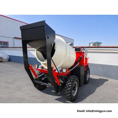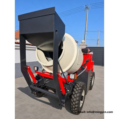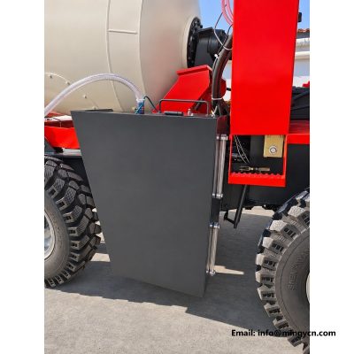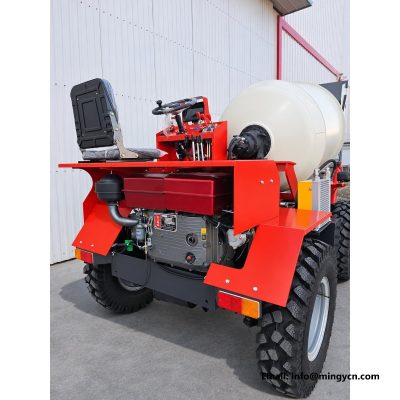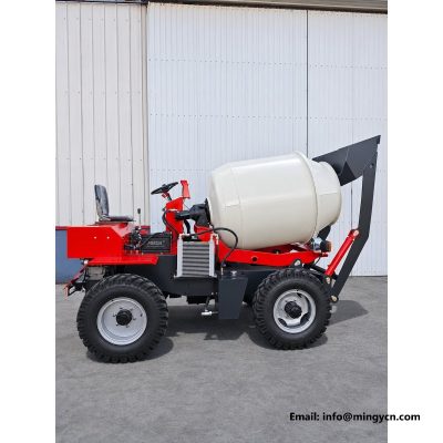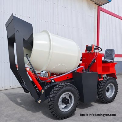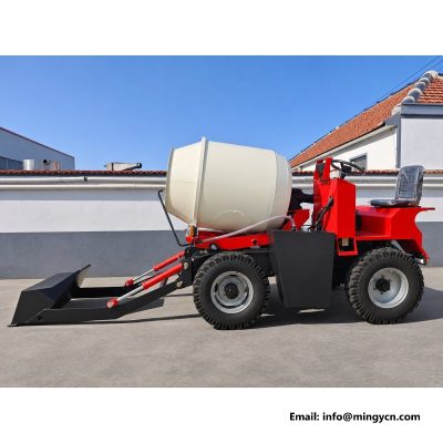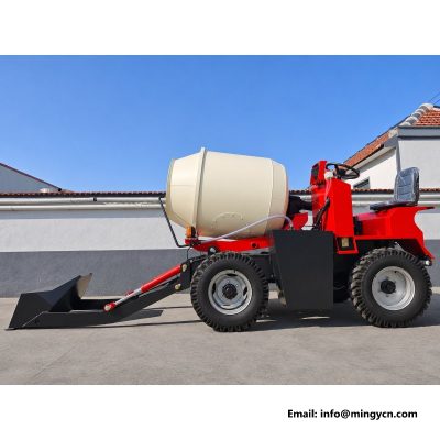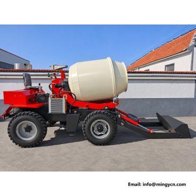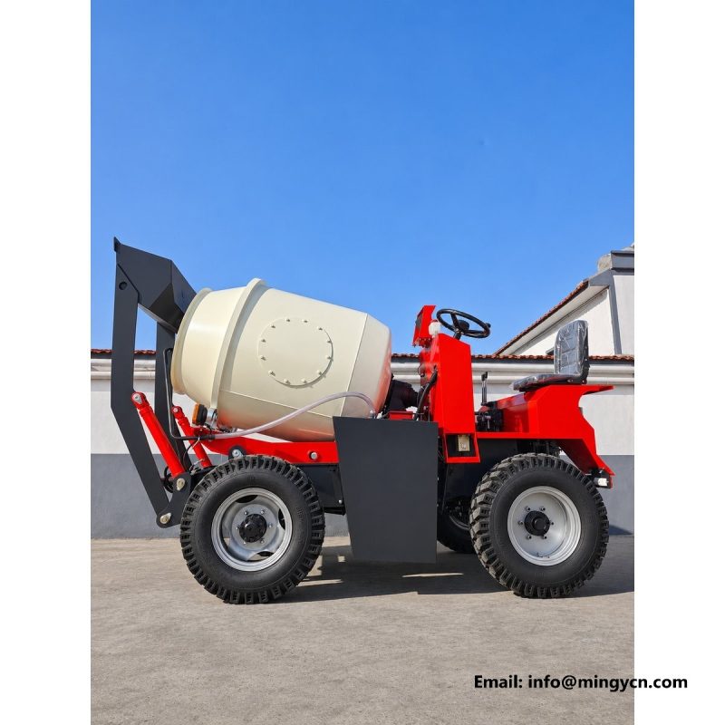
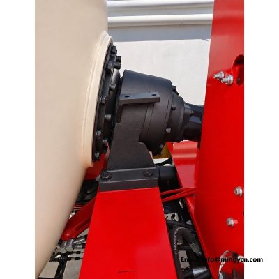
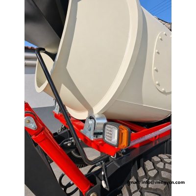
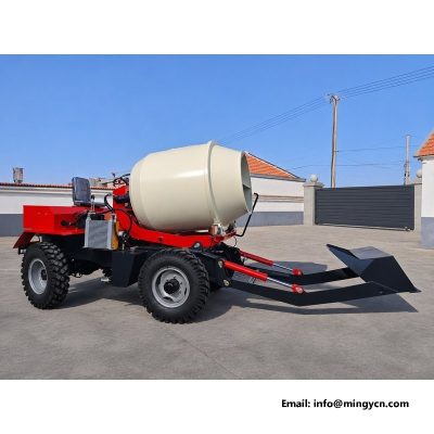
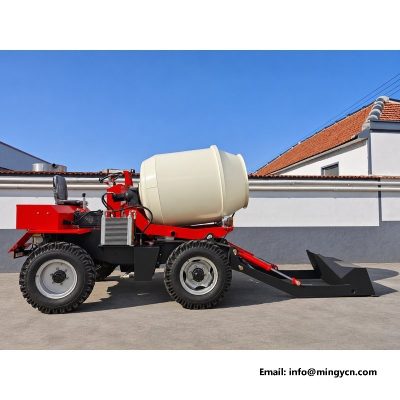
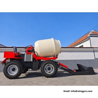
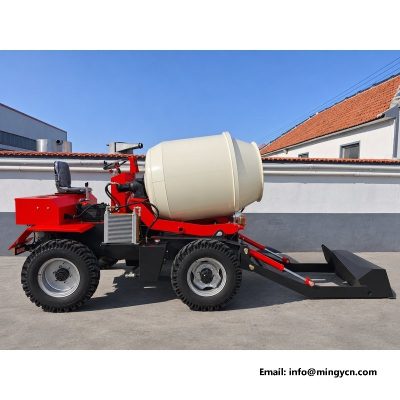
drum drive close-up: motor bolts and coupling
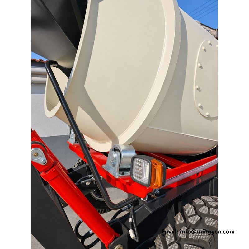
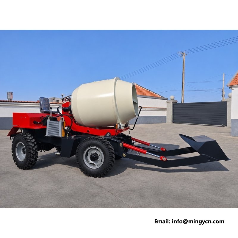
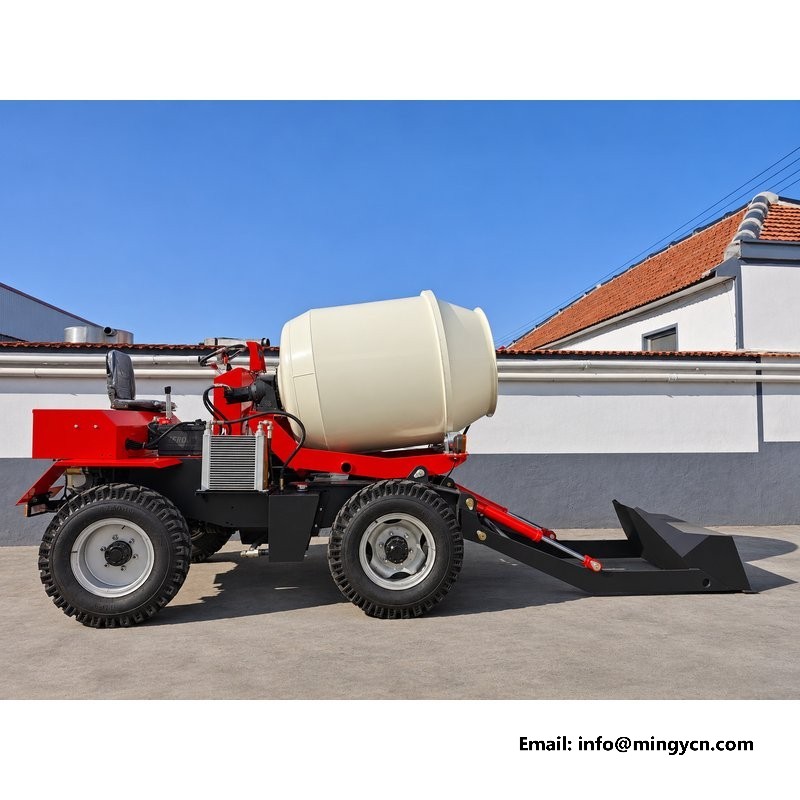
The drive end is where a mixer's reliability is decided, and where photographs are most often flattering rather than informative. These frames stay close to the hydraulic motor, the reduction housing and the ports, with a full machine shot for context. What they are for is fasteners: whether the ring of bolts is even and undisturbed, whether the coupling is covered, whether the hoses arrive at the ports square. Those are the details that separate an assembly built to be serviced from one built only to be shipped. Read them before you read the paint. The machine shot is there only to show where the close-up sits.
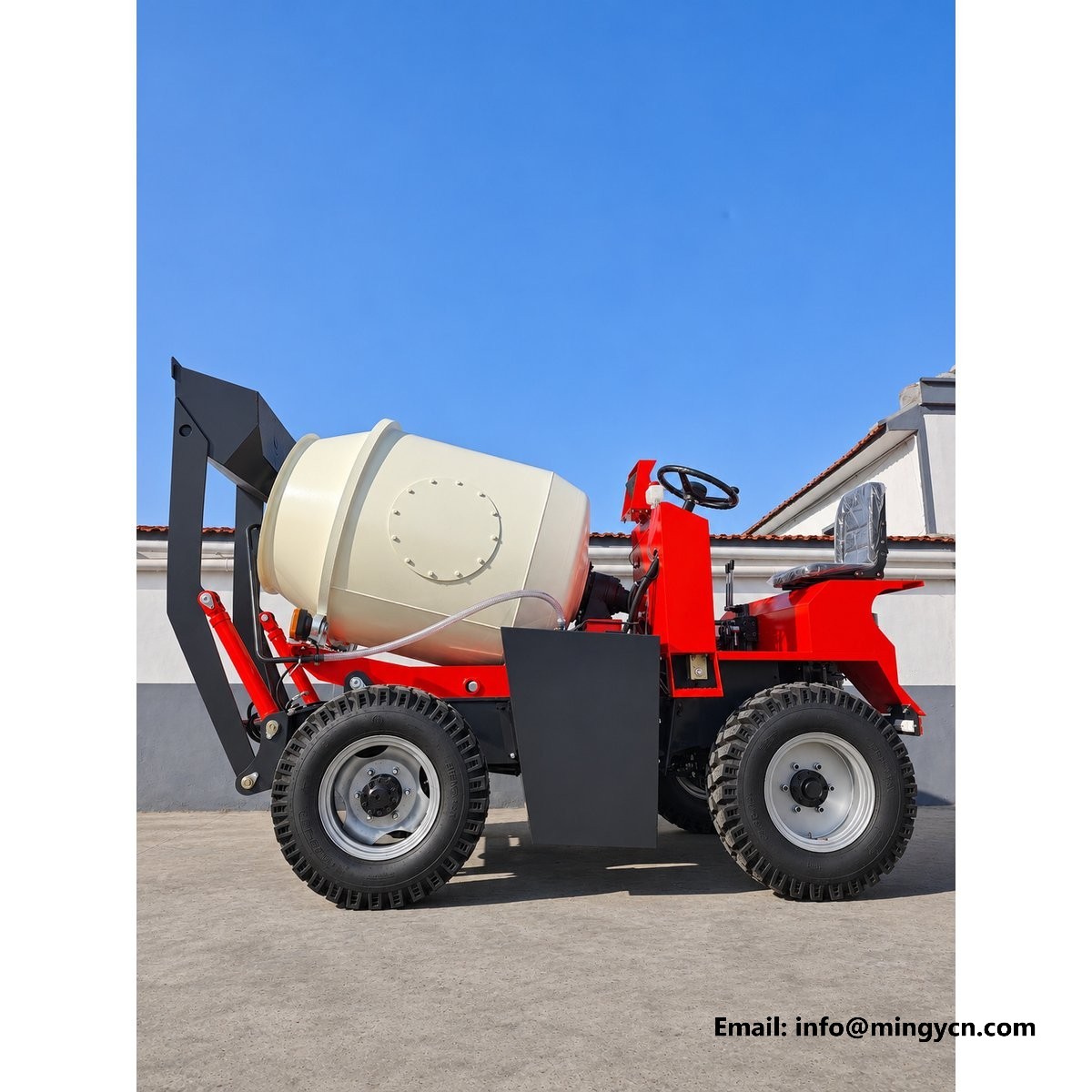
| Specification | 1.5 m³ self loading mixer |
|---|---|
| Drum capacity | 1.5 m³ (1,500 L) |
| Transmission | 4WD, 3 forward + 1 reverse + road gear |
| Engine | Single-cylinder diesel, 25 hp |
The drive end is the least photogenic part of a mixer and the most expensive to repair, which is why a supplier who publishes a clean close-up is telling you something. These frames put the hydraulic motor, the reduction housing and the first length of hose in one view, next to a full machine shot for context. What you are looking for is not shine. It is whether the assembly looks like it was built to be serviced: bolts you can reach with a normal socket, a coupling that is covered, and hoses that arrive at the ports without being dragged sideways. A drive end that is hard to photograph is usually hard to work on. A drive end photographed from three paces away is a picture of a machine; from one pace it is a picture of an assembly.
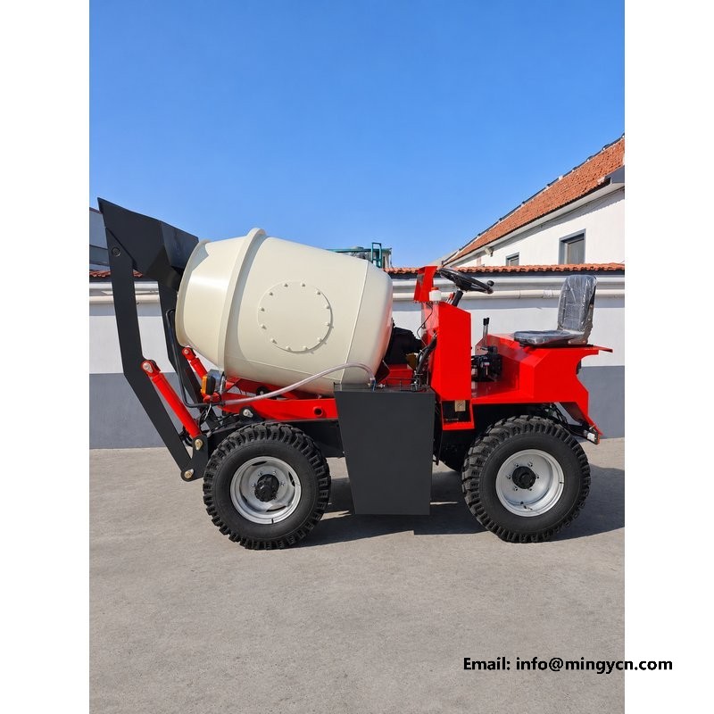
The motor is held to the reduction housing by a ring of bolts, and that ring is where torque loss shows up first. Count them, note whether they are evenly spaced, and look at the washers. A bolt that has been re-torqued leaves a bright ring on the flange; one that has never been touched still carries its original paint. Neither is wrong on a new machine, but a mixed pattern on a used one tells you someone has been in there. Look also at how the heads sit. A head standing proud of the flange has bottomed on a thread rather than clamped the joint, and that joint will weep. Ask whether the bolts carry a grade marking, because a bolt with a blank head is a bolt of unknown strength.
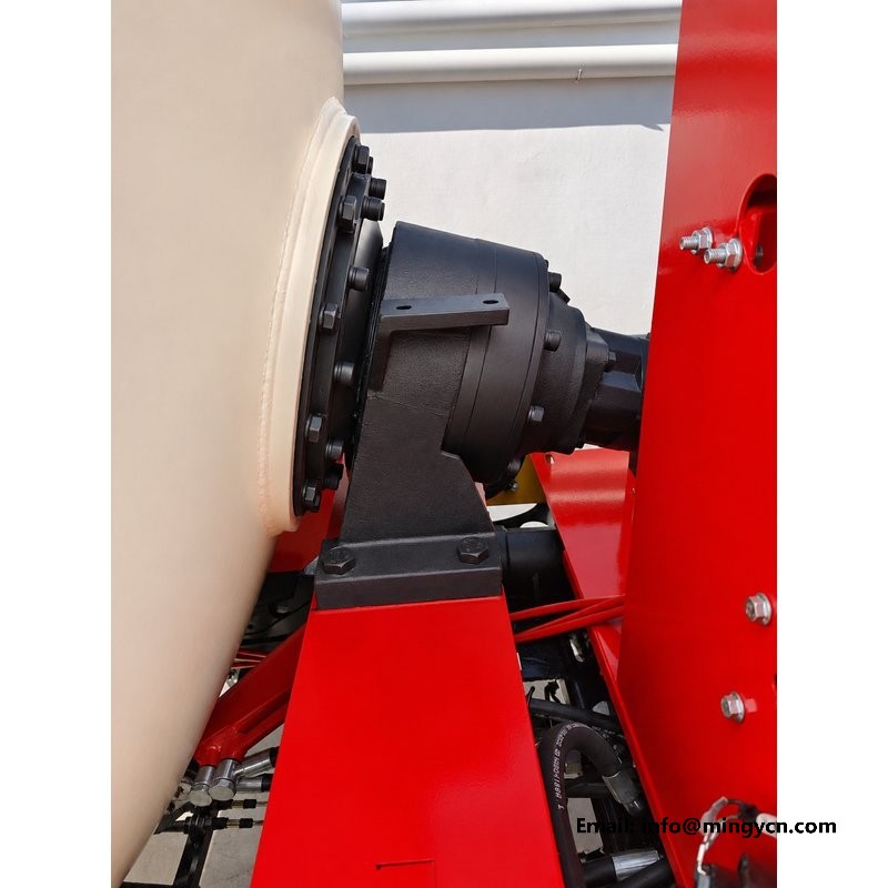
Between the motor shaft and the reduction gear there is a coupling, and its condition decides whether the drum turns smoothly or hammers. In these frames the coupling sits under a cover, which is the right arrangement. An exposed spline on a machine that works in dust is a wear item with a short life. What can still be judged is alignment. The cover should sit square to both housings, with an even gap all round. A cover cocked to one side suggests the motor was bolted down without checking that the shafts lined up, and misalignment eats a coupling faster than load does. If the cover cannot come off for a photograph, ask for the gap between cover and housing to be measured at several points around the circle.
The reduction housing carries its own oil, and the level plug is the detail that matters most in a photograph because it shows whether the unit was filled and checked before dispatch. Look for the plug on the side of the housing, at roughly mid height, and for a fill point above it. Then look for the breather. A gearbox that cannot breathe will push oil past its seals as it warms, and the result is a film that looks like a failed gasket. In the frames here the breather is piped up and away from the housing, which keeps dust and water out of the oil. Wipe the plug before the photograph is taken, not after. A plug that is clean because it was just wiped says nothing about the week before.
The hoses at the motor ports are the highest pressure connections on the drum circuit, and they are also the ones most often assembled in a hurry. What to look for is simple: fittings that enter the port square, a visible thread shoulder rather than a fitting screwed in until it bottoms, and a hose that leaves in line with the fitting rather than being pulled to one side. A hose under lateral load at the fitting works the seal every time the drum reverses. In these frames the runs curve away gently, which is what a proper assembly looks like, and the clamps sit close enough to the ports to take the movement. Note whether the hoses are different sizes or clearly marked, because a circuit reconnected the wrong way round will run the drum backwards.
Not every dark patch is a leak, and the difference matters when you are judging a machine from pictures. A film is a thin, even darkening with dust stuck to it, usually left by assembly oil or a single hot cycle. A weep shows a defined track from one point, with a clean edge where oil has run and stopped. A running drip leaves a wet line and a mark on the ground below. The first is normal, the second needs watching, the third needs fixing before the machine goes to work. In these photographs the area under the motor is dry, and the only sheen sits at the coupling cover joint. Take the photograph before the machine is washed, and again a day later. A leak that reappears after cleaning is a leak that is still active.
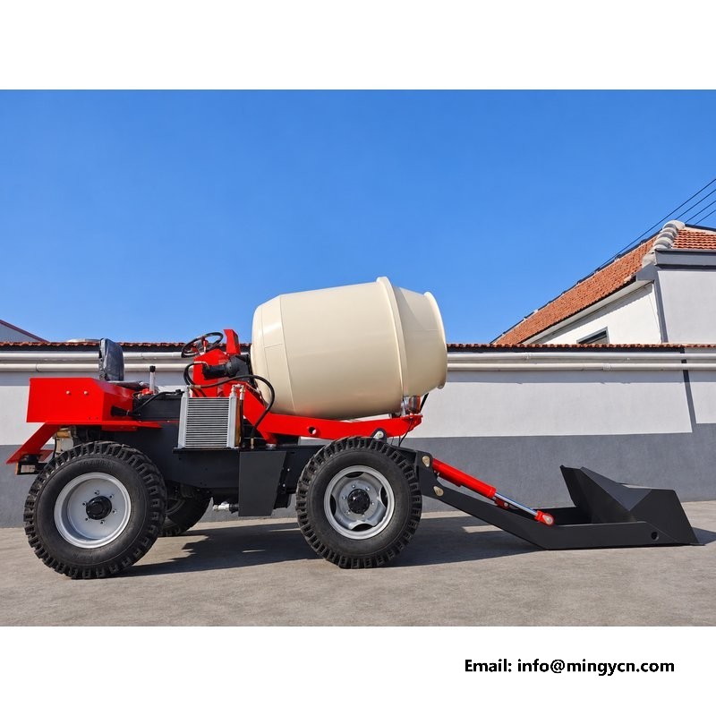
Bolted joints settle. Paint and plating compress, gaskets take a set, and a flange that was tight at the factory can lose preload after the first few shifts of real load. That is why the drive end should be checked again early in the machine's life rather than at some distant interval. The check itself is simple: a wrench on each bolt in sequence, and a mark on the head once it has been done. In the photographs, a paint stripe running across bolt heads and flange is a good sign, because it means someone intends to see at a glance whether anything has moved. Record the date and the hours on the machine when the check is done, so the next owner can see whether the routine was kept.
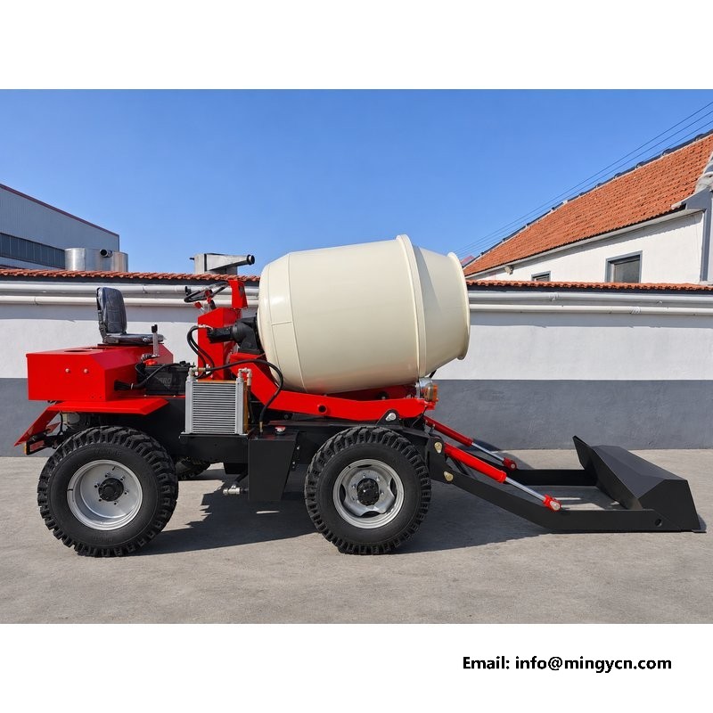
If the motor ever has to come off, the order matters more than the strength of the person doing it. The drum must be empty, the arm down, the circuit depressurised, and the hoses capped before a fitting is cracked. The motor is then supported before the last bolt is drawn, because a unit that heavy will hang on its own shaft and damage the coupling on the way out. In these frames the access is clear enough to get a support under the housing. That is a design decision, not an accident. Ask a supplier to show the machine with the guard off; the answer tells you whether they expect anyone to service it. Photograph the arrangement before anything is loosened, because memory is unreliable once a component is off the machine.
A guard has two jobs, and photographs show only one of them. The obvious job is keeping a hand or a sleeve out of the coupling. The second is keeping dust and water off the seal face, which matters more over years. What to judge is whether the guard comes off with a few fasteners or requires half the assembly to be dismantled. A guard held by a few bolts and located by a tab is easy to refit; one held by more fasteners with no location will fight you every time. In the frames here the cover is a formed pressing with a clean edge, not a flat plate bent by hand. A guard that needs a tool to remove is not a problem, provided the tool is a common one and the fasteners stay with the cover.
A single machine on a remote site should not depend on a next-day delivery for a seal. The drive end has a short list of parts that fail first: the coupling element, the shaft seal, the hose pair and the port fittings. Holding those is cheaper than holding a motor, and they cover most of the failures that stop a pour. The photographs on this page are useful for ordering because they show fitting orientation and the space around the ports. Order from a picture and you will get the right part. Order from a description alone and you will get something close, which is not the same thing at all. Ask which of those parts are standard hydraulic and mechanical sizes, because a seal that must be ordered from the factory is a week of downtime.
Dry metal around the motor and housing, an even ring of bolt heads with intact paint or witness marks, hoses leaving the ports in line rather than pulled sideways, and a coupling that is covered rather than exposed. A single defined weep mark is worth asking about. A general dark film with dust stuck to it usually means oil has been present long enough to collect dirt.
On this layout, yes, but the order matters. Empty the drum, lower the arm, release circuit pressure and cap the hoses before cracking a fitting. Support the motor before drawing the last bolt, because it will hang on its own shaft and load the coupling. Check that the guard comes off with a few fasteners and that there is room to get a support underneath.
For the current specification, build options and a formal quotation for your market, contact MINGYI Machinery. E-mail: sales@mingycn.com | LINE (ID): mingyicn
Hydraulic Valve Block and Drum Drive on the 1.5m3 Self Loading Mixer · Mixing Blades and Drum Interior on the 1.5m3 Self Loading Mixer · 1.5m3 Self Loading Mixer from Every Angle: A Yard Photo Reference